Operation Manual / 4 Product description / A100-M axial
2 Removal and installation / 2.3 Installing the turbocharger
© Copyright 2019 ABB. All rights reserved. HZTL4033_DE Revision C February 2019
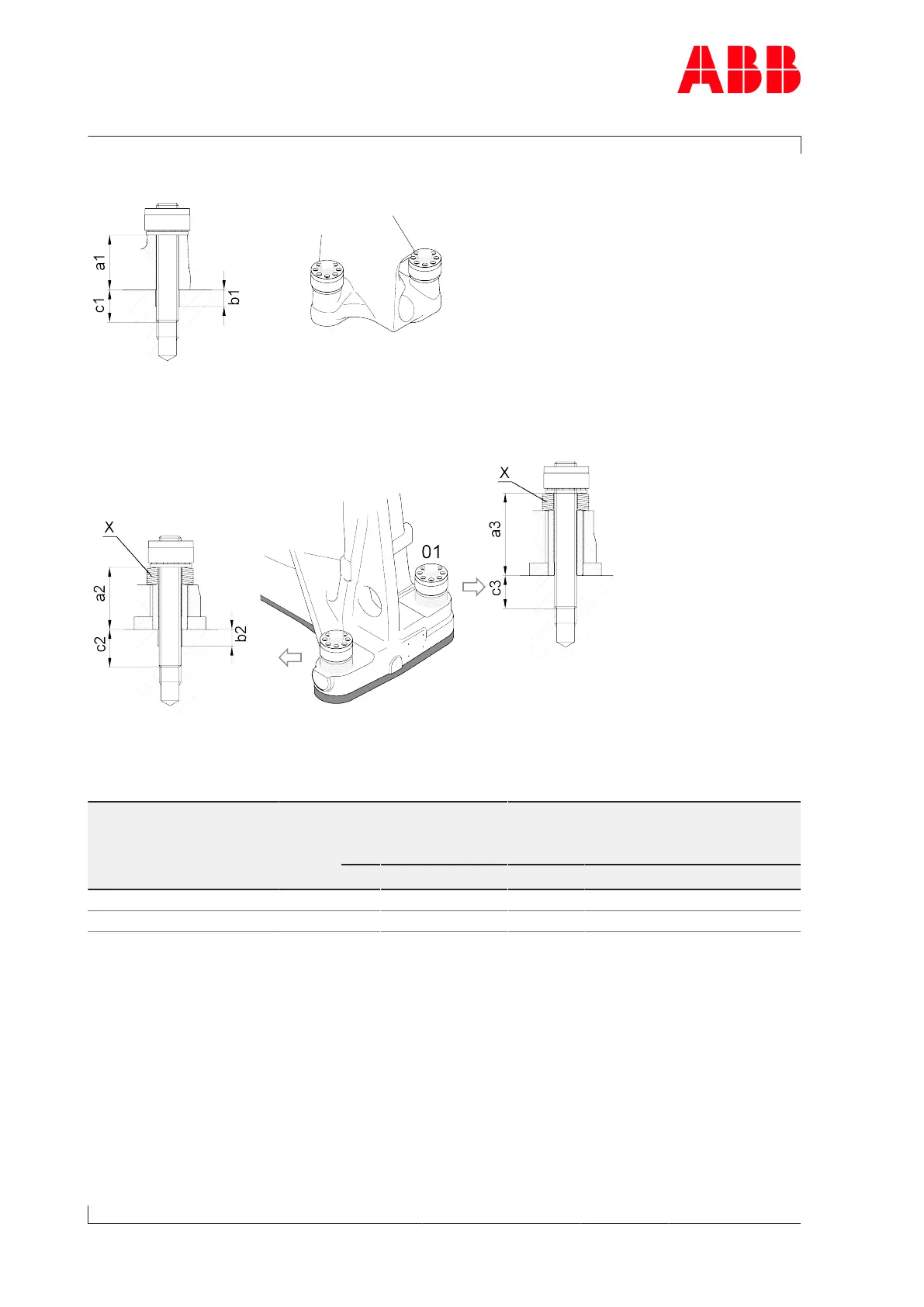
Compressor-end (CE) foot
Fig.11: Compressor-end foot
Turbine-end (TE) foot
Fig.12: Turbine-end foot
Screw dimensions and number of cup springs
Product Foot bolt di-
mension
[mm]
Strength
class
Dimension CE
[mm]
Dimension TE
[mm]
Number
of cup
springs
a1 b1 c1 a2 / a3 b2 c2 / c3 X
A170-M M30 10.9 82 ø32x23 68 94 / 124 ø32x11 56 / 45 9
A175-M M36 10.9 95 ø38x31 85 113 / 148 ø38x12 66 / 54 11
Table3: Foot bolt dimensions
Holes b1/b2 are needed to achieve the required clamping length. An additional drill hole is
not needed at the higher turbine-end foot side (01).
Page 14 / 108
 Loading...