Communication with Modbus
2CMC48001M0201 167 A43/A44
Revision: C User Manual
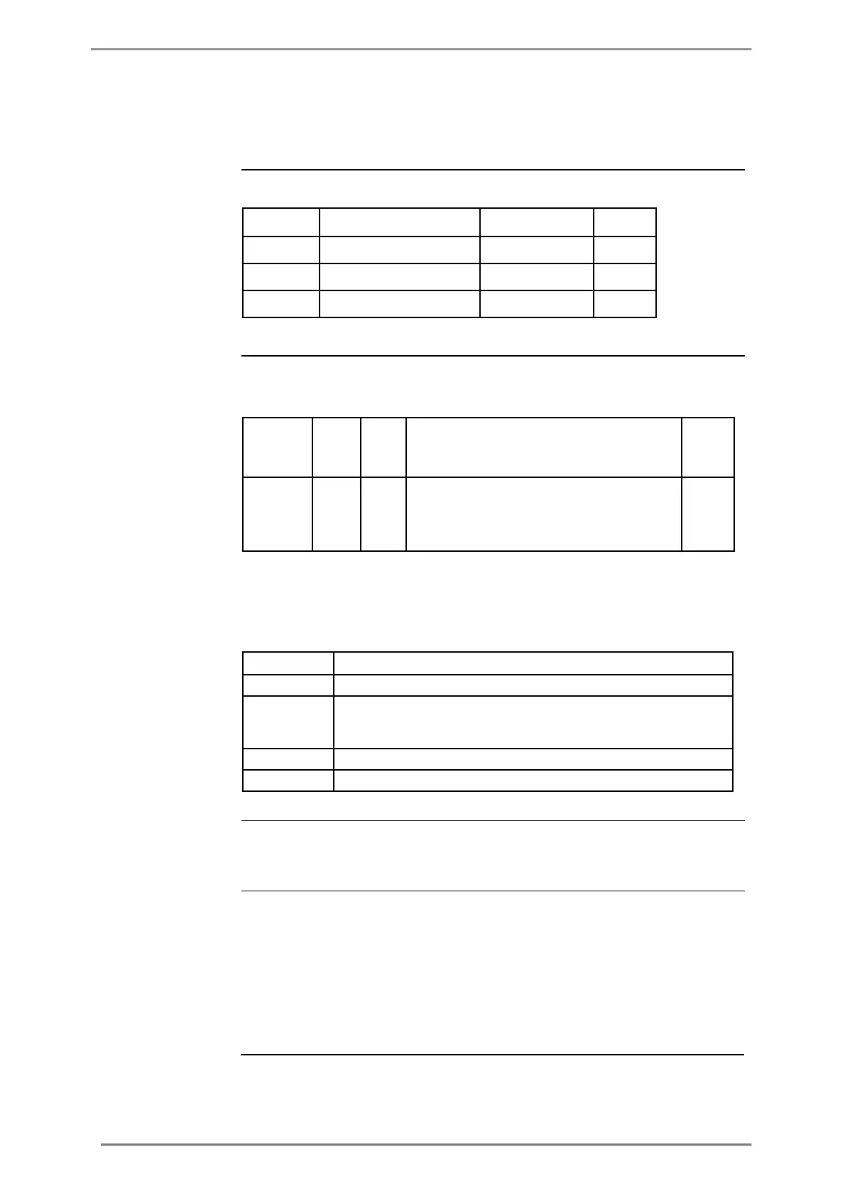
Mapping table The following table shows an overview of the mapping table:
DST start and
end registers
The following table shows the contents of the registers for configuring DST
start. The structure of the DST end registers are the same as for DST start.
Byte 2: Day of week, 1 = monday, 7 = sunday
* Byte 0 is the highest byte of the lowest register.
For month, day of month and day of week wild cards can be used according to
the table below.
2:nd last day of month: 253
DST enabled The DST enabled register decides whether the DST functionality of the meter is
register turned on or not: 0 = off, 1 = on.
Examples of DST Month = 3, Day of month = 254, Day of week = 7, Hour = 2 means last sunday of
Month = 3, Day of month = 254, Day of week = 255, Hour = 2 means last day of
march 02:00, regardless on which weekday it occurs.
Month = 3, Day of month = 2, Day of week = 7, Hour = 2 means second sunday