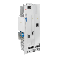
■ Drive module
6
3
+H370
2
4
5
8
11
12
1a
1b
7
16
17
13
19
19
18
20
22
10
21
+B051
+B051
9
14
15
23
24
Telescopic extraction and insertion ramp13Clear plastic shroud to be attached onto the drive
module input power cabling (1a). Entry shroud for
side cabling (1b) (option +B051).
1
Control unit14Clear plastic shrouds to be attached onto the drive
module output power cabling (option +B051)
2
Control cable clamp plate15Clear plastic shroud to be attached on top of the
drive module (entry for top cabling) (option
+B051).
3
Busbars for connecting the drive module to the
LCL filter electrically
16Upper back clear plastic shroud (option +B051)4
Cover for the busbar connection17Lower back clear plastic shroud (option +B051)5
Auxiliary cooling fan18Front clear plastic shroud (option +B051)6
Handle19Input power cable connection terminals (option
+H370)
7
34 Operation principle and hardware description

 Loading...