5 Installation and Commissioning
5.7 Misc. System Connections
100 3HNA009834-001 en Rev.06 Product Manual, Control Cabinet IRC5P
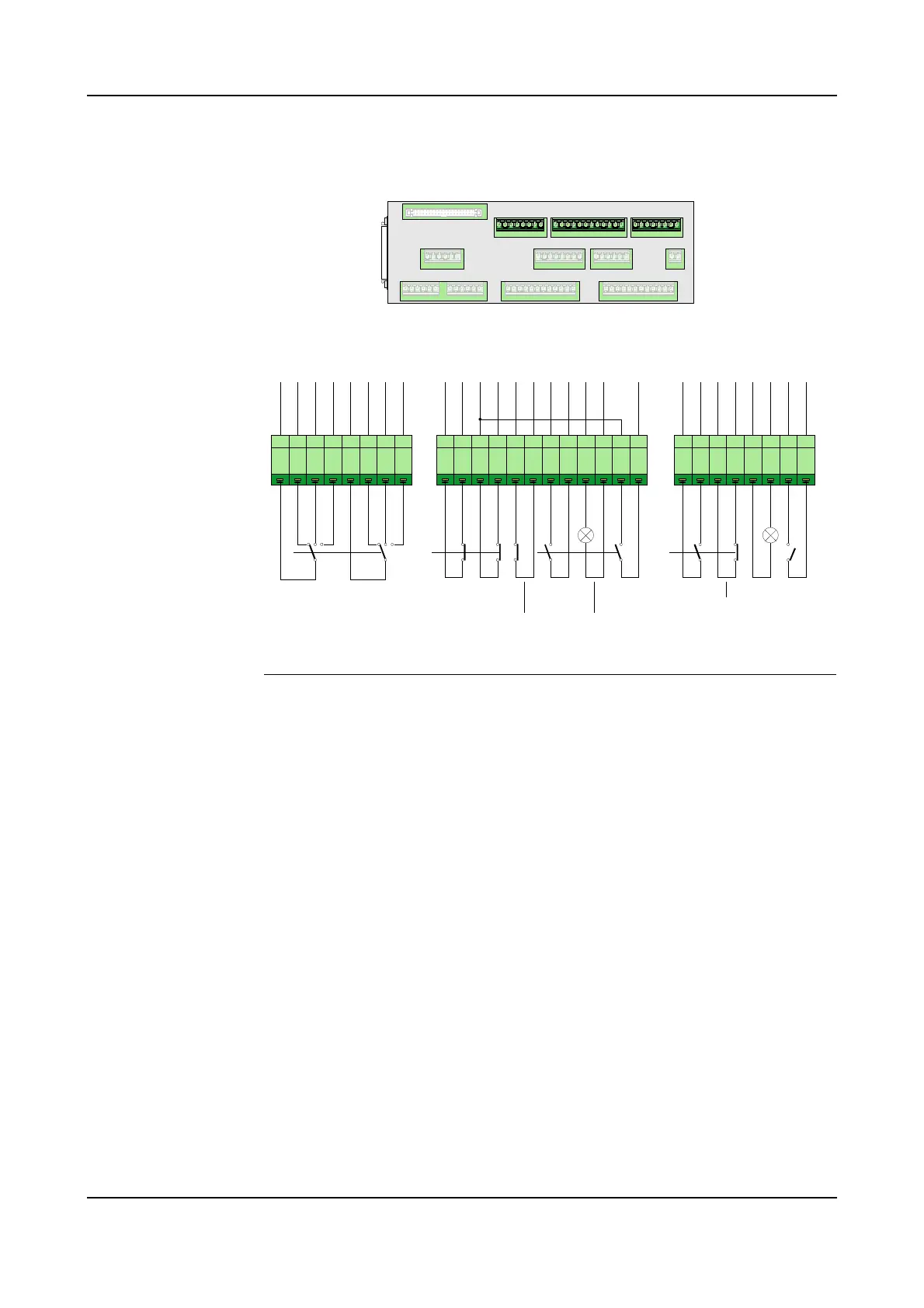
Figure 48 Remote panel connections
References For more details on the function of the switches, see ’Control Panel Description’ on
page 27. For control cabinet internal wiring information on the remote panel
functions, see circuit diagrams supplied with the robot.
1 2 3 4 5 6 7 8 1 2 3 4 5 6 7 81 2 3 4 5 6 7 8 9 10 11 12
X5 X6 X2 X1
X3 X13 X4
X8 X9 X10
X11
X12
X7
SCB-01
P
N
L
_
A
U
T
O
1
S
a
f
e
t
y
_
C
H
_
F
e
e
d
1
P
N
L
_
E
S
1
_
F
E
E
D
P
N
L
_
E
S
1
P
N
L
_
E
S
2
_
F
E
E
D
P
N
L
_
E
S
2
M
O
N
_
E
N
A
P
N
L
_
M
O
F
P
N
L
_
M
O
N
P
N
L
_
M
O
F
1
P
N
L
_
L
M
P
_
M
O
N
G
N
D
P
N
L
_
E
S
_
R
S
T
P
N
L
_
H
V
O
F
1
P
N
L
_
H
V
O
N
P
N
L
_
H
V
O
F
H
V
_
P
N
L
_
H
S
P
N
L
_
L
M
P
_
P
U
R
G
N
D
P
N
L
_
M
A
N
1
P
N
L
_
M
A
N
F
S
1
P
N
L
_
A
U
T
O
2
S
a
f
e
t
y
_
C
H
_
F
e
e
d
2
P
N
L
_
M
A
N
2
P
N
L
_
M
A
N
F
S
2
Emergency
Stop
Motor Off
C
h
1
C
h
2
C
h
1
C
h
2
X9
HV On
X10
Motor
On
C
h
2
Motor On Lamp
Emy Stop
Reset
C
h
1
C
h
2
HV Off
Purge
Lamp
X8
C
h
2
Mode Selector
C
h
1
P
N
L
_
L
M
P
_
T
S
T
+
2
4
V
_
I
O
Lamp
Test
C
h
1