5 Installation and Commissioning
Product Manual, Control Cabinet IRC5P 3HNA009834-001 en Rev.06 79
5.5 Cabin Safety System Connections
5.5.2 Cabin Safety Connection Overview
General Cabin safety connections are a number of interlock functions which can/must be
installed to provide personnel safety and to ensure safe operation of the cabin and
robot paint systems.
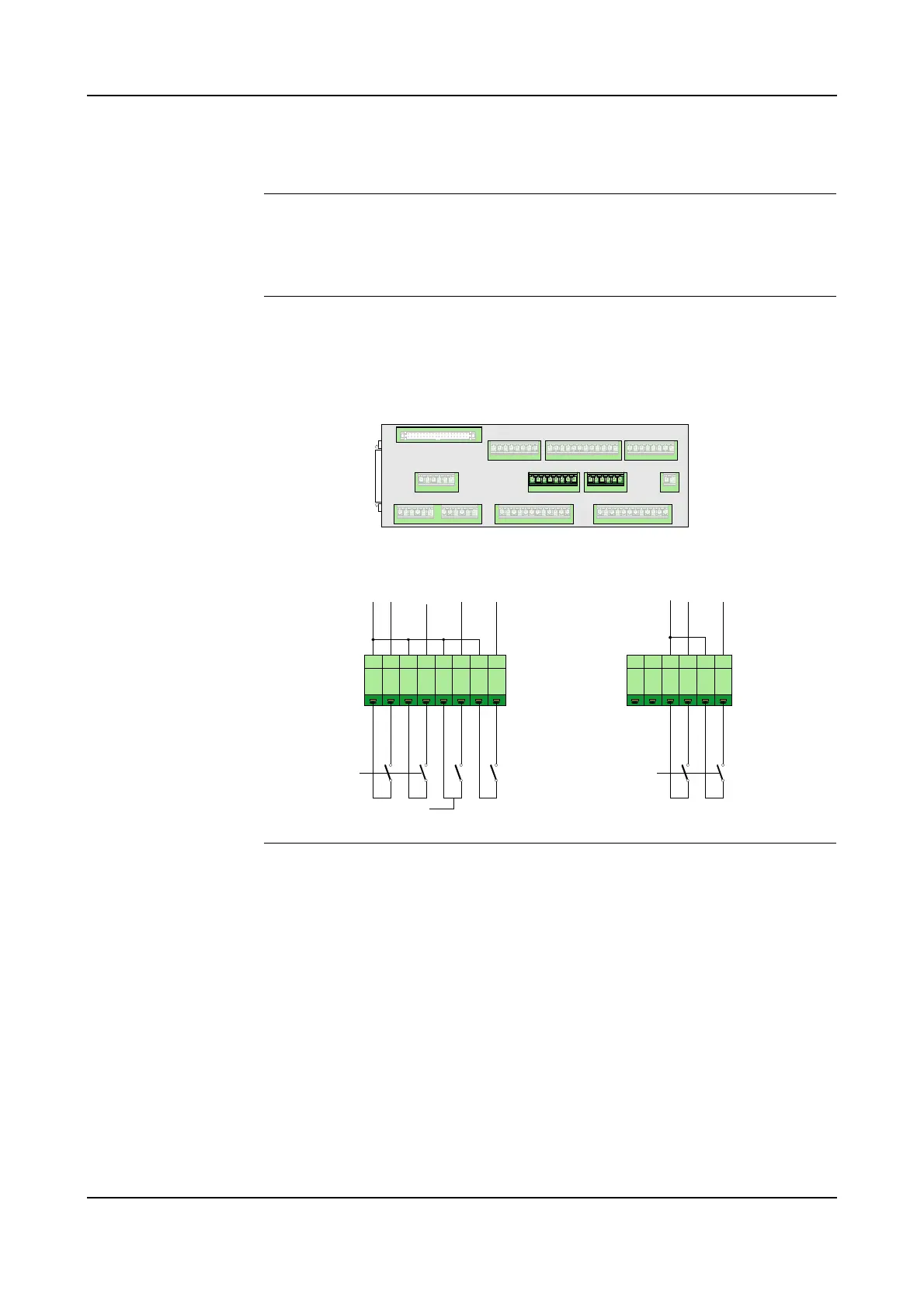
Description The illustration below shows an overview of the cabin safety connections and the
procedure gives a short description of the connections which must/may be
connected with references to where complete information can be found.
Figure 34 Cabin interlock connections
Procedure 1. Connect Cabin Interlock switches in the cabin interlock chain to disable paint
functions when certain vital cabin functions are not present, like cabin
ventilation. For information, see ’Cabin Interlock’ on page 80.
2. Connect High Voltage Interlock switches on the cabin entrance door to prevent
people from entering the cabin when high voltage is ‘on’. For information, see
’High Voltage Interlock’ on page 81.
3. If required, install System 2 Interlock switch for bell applicator, paint pumps or
DCU (CBS). For information, see ’System 2 Interlock’ on page 82.
4. If required, connect Process Interlock switch for switching off all paint related
functions. For information, see ’Process Interlock’ on page 83.
5. If required, install Emergency Shut-Down valve in manipulator. For
information, see ’Emergency Shut Down Valve’ on page 85.
1 2 3 4 5 61 2 3 4 5 6 7 8
+
2
4
V
D
C
E
X
T
_
C
A
B
_
I
L
C
K
1
E
X
T
_
C
A
B
_
I
L
C
K
2
E
X
T
_
S
Y
S
_
I
L
C
K
_
I
N
E
X
T
_
F
I
R
E
_
I
L
C
K
X5 X6 X2 X1
X3 X13 X4
X8 X9 X10
X11
X12
X7
SCB-01
X3
X13
E
X
T
_
H
V
_
I
L
C
K
1
E
X
T
_
H
V
_
I
L
C
K
2
+
2
4
V
D
C
High Voltage Interlock
C
h
1
C
h
2
Cabin
Interlock
System 2 Interlock
Process
Interlock
C
h
1
C
h
2