5 Installation and Commissioning
Product Manual, Control Cabinet IRC5P 3HNA009834-001 en Rev.06 61
5.3 System Interconnections
5.3.4 Connectors
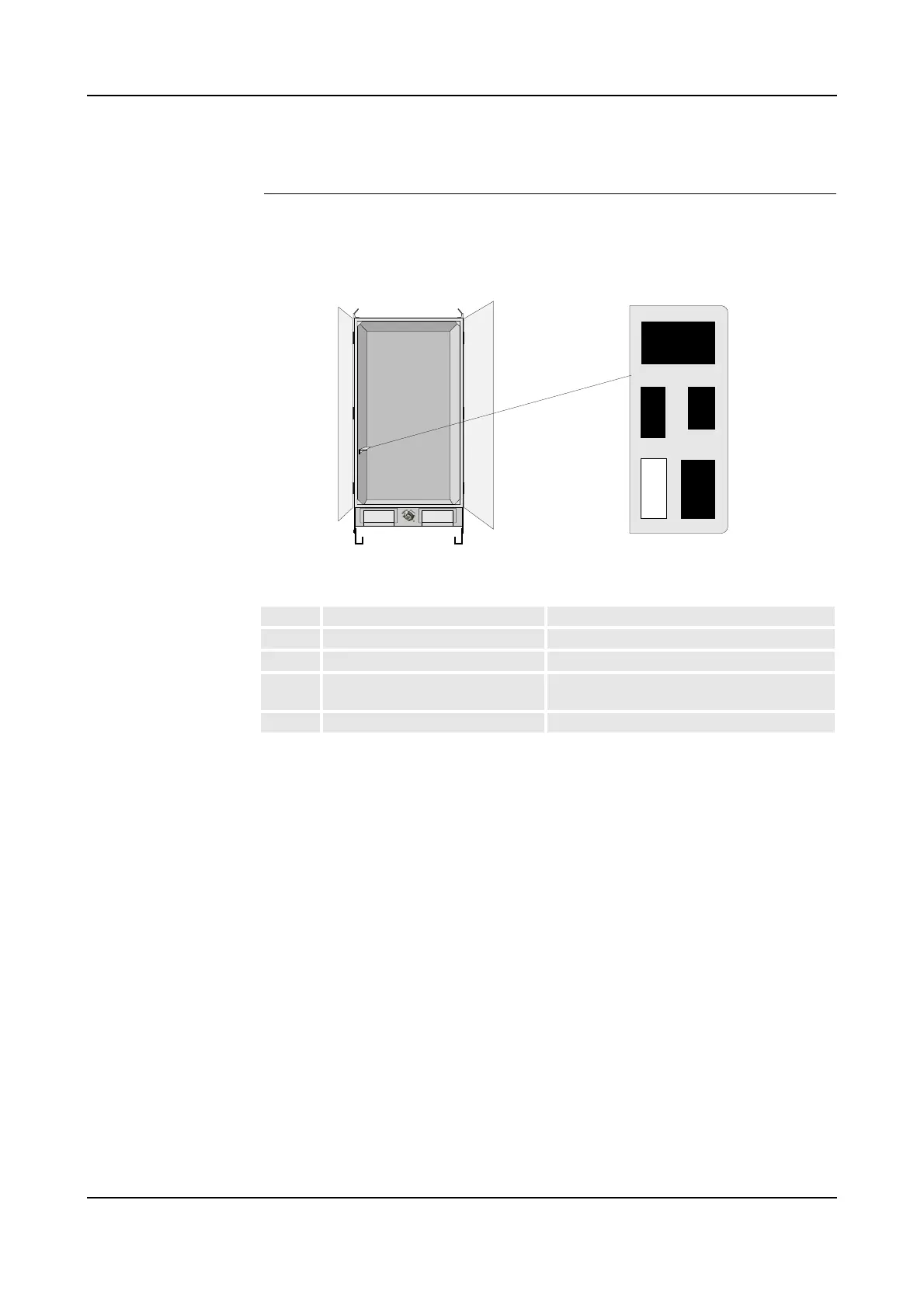
Connector Overview This section shows the location of the connectors on connector brackets in the
control cabinet side wall.
Figure 28 Location of connectors
Identification of the signals in the above connectors can be found on the following
pages.
Conn. Description Comment
X11 Motor power for manipulator Standard connector (Not used for IRB 5500)
X12 +24VDC for manipulator Standard connector (Not used for IRB 5500)
X111 Paint pumps in manipulator / pump
cabinet or 8th axis connector
Optional connector
X211 CBS robot Optional connector
X211
X12
X11
Spare
X111
Connector bracket - top view