7 Repair
Product Manual, Control Cabinet IRC5P 3HNA009834-001 en Rev.06 133
7.3 Replacement of System LED Board, ALED
7.3 Replacement of System LED Board, ALED
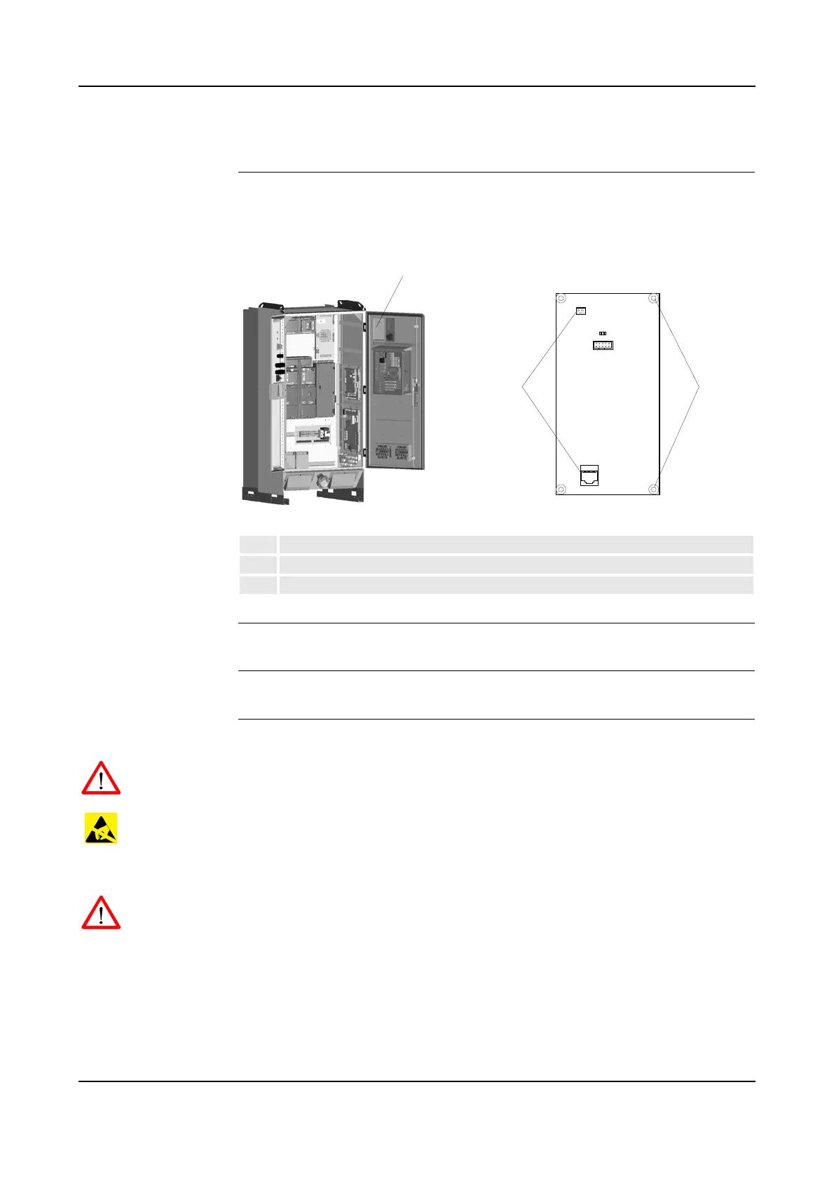
Location The System LED Board is located at the upper right corner (front view) of the
controller front door as shown below.
Figure 68 System LED board, ALED
References – For information on the ALED board, see ‘Unit Description, IRC5P’
Tools and Items – Hand tools
Removal The procedure describes how to remove the system LED board.
WARNING! No repair work must be performed on the robot before the safety
regulations in ’Safety’ on page 13 have been read and understood.
CAUTION! The unit is sensitive to ESD. Before handling the unit, please observe
the safety information in ’ESD Precautions’ on page 130.
1. Turn the electrical disconnect switch ‘off’ and lock switch in ‘off’ position.
WARNING! Make sure that the mains switch is ‘off’ and locked in ‘off’ position
before continuing. Also make sure that possible other connected systems are ‘off’.
2. Open controller front door and locate the system LED board (68/1).
3. Disconnect connectors.
4. Remove 4 attachment screws. Retain screws for installation of new board.
5. Remove board. Note orientation of board.
1 System Led Board, ALED
2 Connectors
3 Attachment screws