5 Installation and Commissioning
5.1 Introduction
44 3HNA009834-001 en Rev.06 Product Manual, Control Cabinet IRC5P
5.1.4 Safety Connection Board
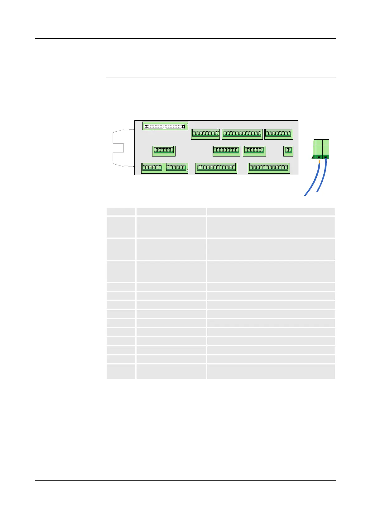
Connection Overview The following illustration and table show the connectors on the Safety Connection
Board, SCB.
Figure 18 Safety Connection Board, SCB
Conn. Connection Reference
SCB - X1 Emergency stop (Cat.0)
Auto mode stop (Cat.0)
Test mode stop (Cat.0)
’Robot Safety System Connections’ on page 64
SCB - X2 General mode stop (Cat.0)
Delayed stop (Cat.1)
Emy stop feedback
’Robot Safety System Connections’ on page 64
SCB - X3 Cabin interlock
System 2 interlock
Process interlock
’Cabin Safety System Connections’ on page 78
SCB - X4 Ext emy stop chain supply ’Robot Safety System Connections’ on page 64
SCB - X5 Encoder input 1 ’Encoder and Sync Switch Installation’ on page 86
SCB - X6 Encoder input 2 ’Encoder and Sync Switch Installation’ on page 86
SCB - X7 Encoder input 3 ’Encoder and Sync Switch Installation’ on page 86
SCB - X8 Remote panel connection ’Remote Panel Connections’ on page 99
SCB - X9 Remote panel connection ’Remote Panel Connections’ on page 99
SCB - X10 Remote panel connection ’Remote Panel Connections’ on page 99
SCB - X11 System connector System connection to SIB - X11
SCB - X12 System connector Panel connection to SIB - X10
SCB - X13 Emergency stop reset
High voltage interlock
’Robot Safety System Connections’ on page 64
’Cabin Safety System Connections’ on page 78
SCB-01
X5 X6 X2 X1
X3 X13 X4
X8 X9 X10
X11
X12
X7
X5 X6 X2 X1
X3 X13 X4
X8 X9 X10
X11
X12
X7