3 System Description
3.2 Basic Design
22 3HNA009834-001 en Rev.06 Product Manual, Control Cabinet IRC5P
3.2.4 Purge System
General When the robot is installed in an area where explosion hazard is present, it is
equipped with a purge system. The purpose of this system is to apply compressed
air in the manipulator. The compressed air is kept at a higher pressure than the
atmospheric pressure and so preventing hazardous gases from entering the
manipulator interior.
For more details on the purge unit, see ‘Unit Description, IRC5P’, Purge System.
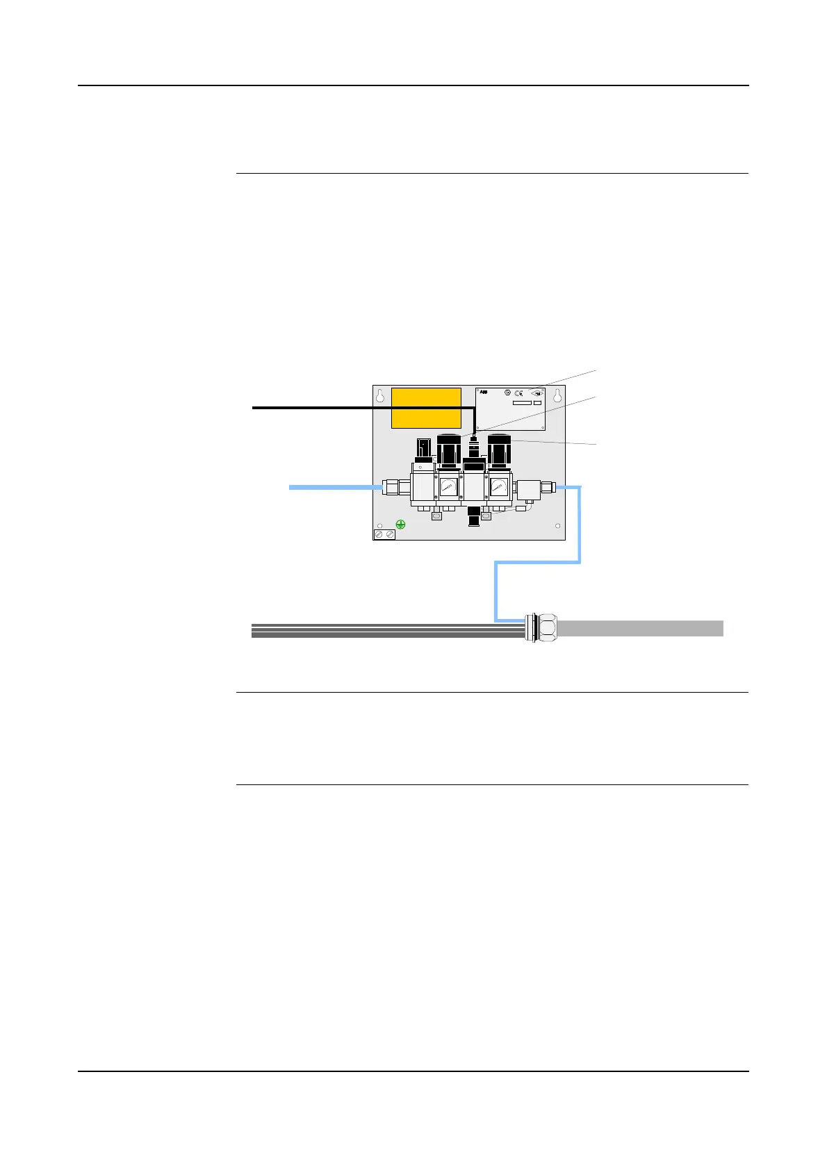
Figure 5 Purge unit design
Description The purge valve assembly includes various valves for controlling and regulating the
purge air supply to the robot. Supply air is connected to the purge unit and, via the
control valves, routed to the manipulator via the purge connector and flexible hose.
Versions Different versions of the purge unit are available:
The purge unit shown in the above illustration is used for all stand-alone robots.
For robots operating on a trolley, a different type of purge unit, called ‘Purge Unit
with Connector Box’, is used. This purge unit includes a purged chamber with cable
connections. The main reason for using this type is to provide flexible cables via the
trolley cable chain. For information on this purge unit type, see ’Purge Unit
w/Connector Box’ on page 111.
Purge supply to dry filtered
air only (instrumental air)
Purge pressure:
WARNING! PRESSURIZED AIR
Not e:
3 bar (45 psi)
Mainte nance p ressure: 0,5-1 bar
TURN OFF MAIN AIR-TAB BEFO RE
WORKING ON EQUIPMENT
Purge time: See machine specification
PO Box 265, N-4349 B ryne
ABB AS, Robotics
0470
APPROVED
Type:PURGE CONNECTOR BOX
Dwg.No.: 3HNM 01201-1
Part of :PU RGE SYSTEM Dwg.N o.3HNE 06486- 1
NEMKO 02AT EX189U
Protective gas :........................... Instrumental air
Purge Suppl y press ure :............ M in.3.0 max.5.0 bar
Maintenanc e Supply press ure :. M in.0. 5 max.1.0 bar
Leaquage C ompensation : ........... 5 -20 Nl/min.
Maintenanc e press ure :................. Min. 0.8 mbar
Enclosure Pressure :..................... Max. 500 mbar
BatchSerial No.
INTRINSICALLY SAFE SIGNALS Cl. I.II. Div. 1 , Gr. A - G
[EEx pib] IIB
II ( 2) G,D
Supply air
Flexible hose
to manipulator
Motor and
control signals
Purge valve
control signal
Purge connection
Purge valve assy'
Purge air
hose
Purging (Flushing)
pressure regulator
Maintenance pressure
regulator
Identification label