5 Installation and Commissioning
5.6 Encoder and Sync Switch Installation
94 3HNA009834-001 en Rev.06 Product Manual, Control Cabinet IRC5P
5.6.6 Sync. Switch Installation
General The sync switch may be positioned to detect the work object suspension or the work
object directly.
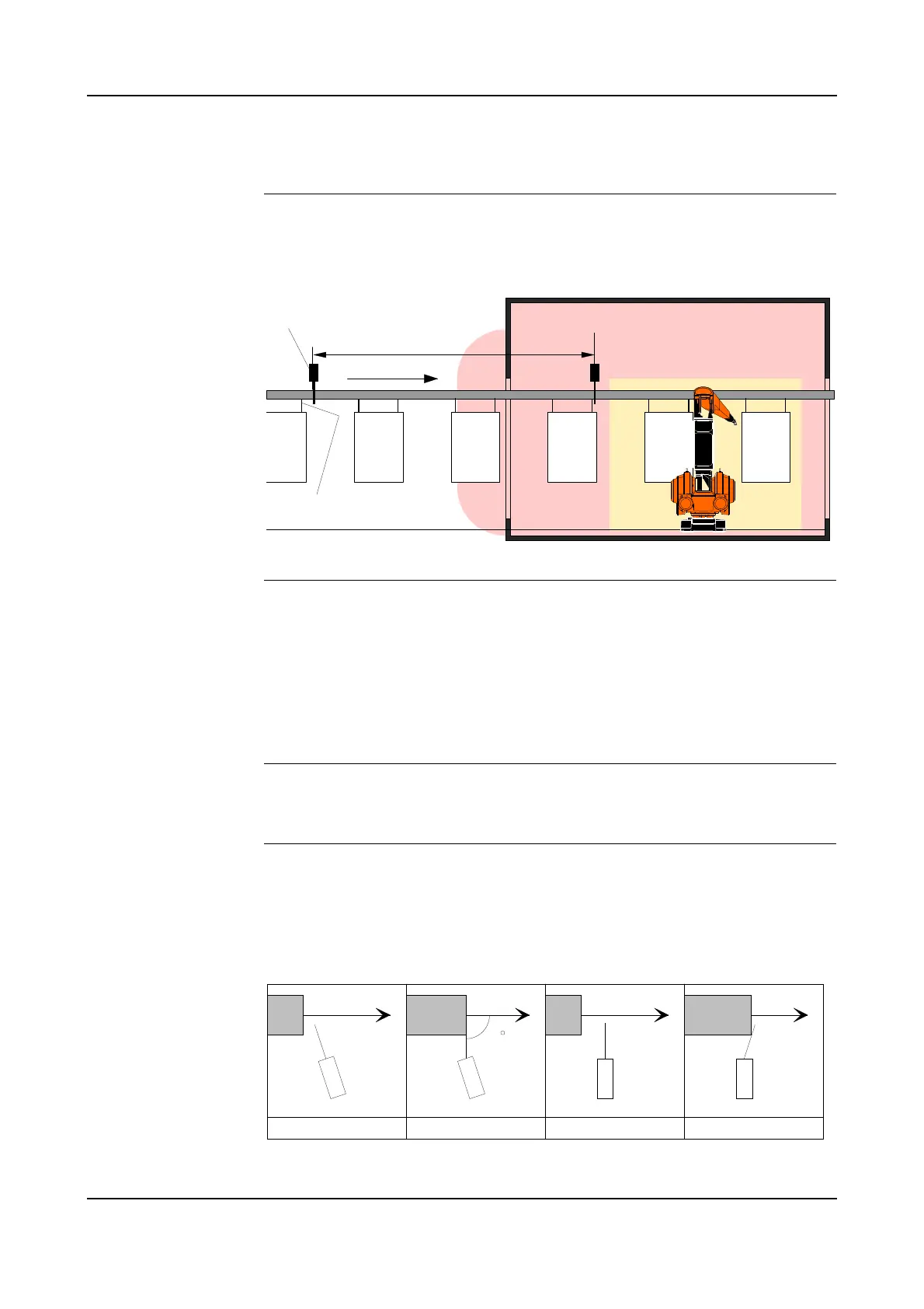
Figure 42 Location of sync switch in an installation
Location of Switch To reduce possible variation in the synchronization signal due to uneven conveyor
motion, swinging of work objects etc., the switch should be placed as close to the
robot as practically possible.
The switch may also be placed outside the hazardous area. This location must be
used if a non-ex switch and non-ex connection is used. The switch can be installed
on a bracket mounted on the conveyor.
Initiator Mounting If an initiator is used, the initiator should be installed to detect the object directly, or
detecting the object suspension (a flag on the suspension) etc.
‘Normal’ Switch
Mounting
If a ‘normal’ switch is used, the switch arm must be in a perpendicular position in
relation to the work object when the switch is activated. If the switch is installed as
indicated in the two illustrations at the right, there is a risk that the work object (or
suspension) will slide on the switch arm, causing inaccurate switching.
Figure 43 Sync switch mounting
Robot
working
area
0.0 point
Non-ex
Sync switch
Sync switch
trig point
Queue tracking distance
Spray booth
Hazardous area
Hazardous area
outside entrance
Ex Sync switch
90
CorrectCorrect Not correct Not correct