5 Installation and Commissioning
Product Manual, Control Cabinet IRC5P 3HNA009834-001 en Rev.06 55
5.3 System Interconnections
5.3.2 Electrical Interconnections IRB 52, IRB 5400, IRB 580, IRB 540
Procedure Perform following procedure to interconnect control cabinet, manipulator, purge
unit and if applicable pump system or CBS robot.
Note: If ‘purge unit w/connector box’ is used (trolley robot), connect cables from
robot in purge unit and purge sensor cable to connector AX1-X4 on purge unit as
described in ’Connecting Manipulator to Purge Unit’ on page 112.
1. Open control cabinet front door.
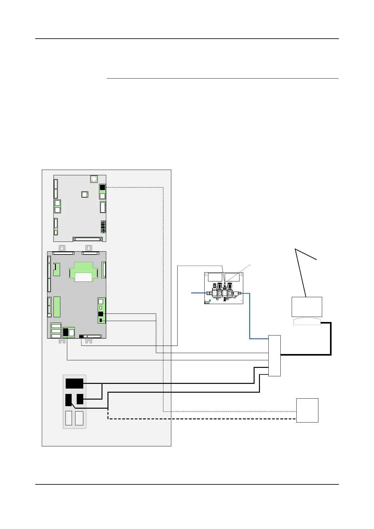
Figure 24 Electrical interconnections IRB 52, IRB 5400, IRB 580, IRB 540
2. Connect purge valve cable to connector AX1-YV1 on purge unit.
X12
X11
X111
Communication robot
Purge valve
connector
AX1-YV1
Intrinsically safe signals
Purge unit
valve assembly
X6
Purge air hose
Robot power
Purge valve
X22
X4
MIB
Pump power
Control cabinet
Pump power
Communication pressure sensors
*1 Connection for pumps in robot
*2 Connection for pumps in pump cabinet
X21
SMU battery power
Purge sensor
Flexible hose
Paint Robot
Purge connection
Pump cabinet
*1
*2
Connector bracket on
cabinet left side wall
Air conn.
PIB-01
Power
Ethernet 1
Ethernet 2
Ethernet 3
CAN1 MS/NS 3
CAN2 MS/NS 3
Ext SPI1
Ext SPI2
ALED SPI
X5
X7
X6
X3
X1
X11
X2
X9
X10
X12
X4
X17
X13
X15
X16
X18
BAR CODE AREA
3HNA 000000-001 NNNNNN
PIB-01
X5
X7
X6
X3
X1
X11
X2
X10
X12
X4
PIB
X9