5 Installation and Commissioning
5.6 Encoder and Sync Switch Installation
92 3HNA009834-001 en Rev.06 Product Manual, Control Cabinet IRC5P
Encoder Connection -
General Information
The encoder is connected to encoder inputs on the SCB board in the control cabinet.
The connection of the encoder may be performed in different ways as described in
the following:
• A single encoder for normal conveyor tracking.
• One encoder used to serve two or more robots.
• Two encoders to provide a backup encoder.
CAUTION! The encoder must be connected using a screened cable. If the cable is
long, special considerations concerning generated spike pulses must be taken. - Ref:
’Encoder Noise Suppression’ on page 88.
Connecting Encoder to
Control Cabinet
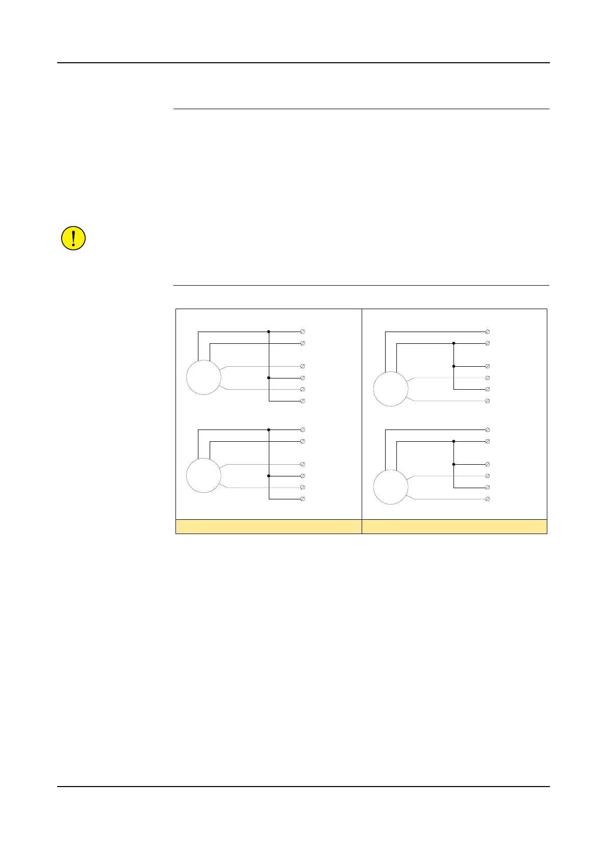
Figure 40 Encoder connection in control cabinet
The encoder is connected to inputs on connector X5 - X7 on the SCB board in the
control cabinet as shown above and in Figure 38.
The 2 phases, A(0°) and B(90°), must be connected so that the encoder counts ‘up’
when the conveyor moves forwards and counts ‘down’ when the conveyor moves
backwards. For information on finding the rotating direction, see ’Rotating
Direction’ on page 88.
Connections for the second encoder shown above can only be used if the 2nd
encoder is to be used as backup.
The 2 LEDs for each of the encoders on the cabinet LED display will flash to show
the pulses from the encoder. By running the conveyor extremely slowly, these
indicators can be used to verify the pulses from the encoder.
Encoder 2
Encoder 1
Connection for PNP encoder Connection for NPN encoder
B (90°)
A (0°)
GND
24VDC
P_ENC1_A+
P_ENC1_ A–
P_ENC1_ B+
P_ENC1_ B–
0 Volt
+24 VDC
1
2
3
4
5
6
SCB-X5
Encoder 2
B (90°)
A (0°)
GND
24VDC
P_ENC2_A+
P_ENC2_ A–
P_ENC2_ B+
P_ENC2_ B–
0 Volt
+24 VDC
1
2
3
4
5
6
SCB-X6
B (90°)
A (0°)
GND
24VDC
P_ENC2_A+
P_ENC2_ A–
P_ENC2_ B+
P_ENC2_ B–
0 Volt
+24 VDC
1
2
3
4
5
6
SCB-X6
Encoder 1
B (90°)
A (0°)
GND
24VDC
P_ENC1_A+
P_ENC1_ A–
P_ENC1_ B+
P_ENC1_ B–
0 Volt
+24 VDC
1
2
3
4
5
6
SCB-X5