158 Commissioning instructions Manual Power Quality Filter PQFS
• Install the capacitor banks upstream of the active filter CT measurement
location
• Set the filter in Mode 3
− In installations where detuned banks are present, it is recommended not to select
harmonic orders below the tuning frequency of the detuned banks. Table 54
indicates the harmonics recommended to be deselected for different types of
detuned banks.
Table 54: Recommended harmonics to be deselected for different detuned bank types
Detuned bank type Harmonics recommended to be deselected
5.67 % 2, 3, 4
6 % 2, 3, 4
For other types of detuned bank please contact your ABB Service provider to
evaluate the resonance frequency and the harmonics that are recommended to
be deselected.
When background distortion is present on the network and detuned capacitor
banks are installed adjacent to the active filter but connected downstream of
the filter CTs, filter resources will be lost. To overcome this, it is recommended
to either connect the detuned capacitor bank upstream of the filter CTs or to
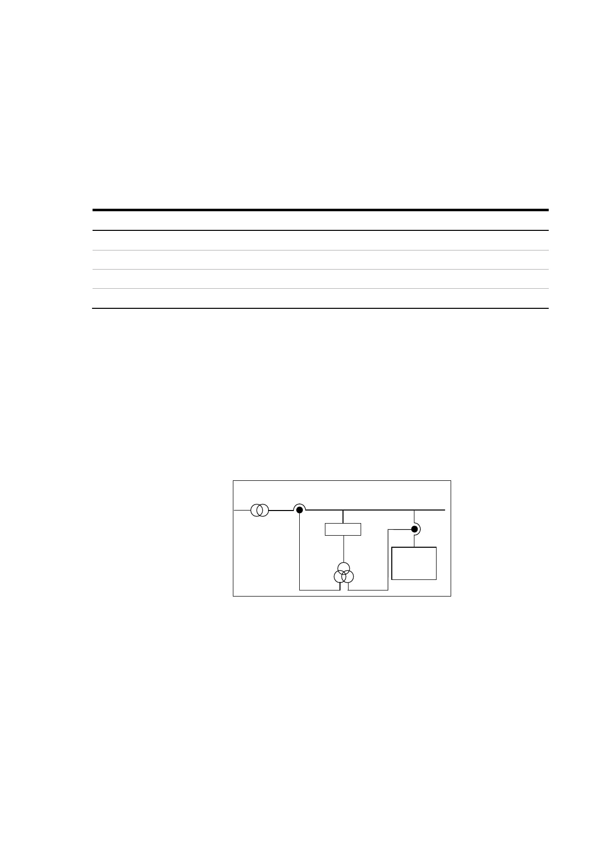
use the CT connection approach shown in Figure 81.
Figure 81: Connection approach for installations where detuned capacitor banks are installed
adjacent to the active filter but downstream to the active filter CTs (background distortion
present)
− In installations where active filters and passive filters are present, the active
filters must be installed downstream of the passive filter. If this is not possible,
the CT connection scheme of Figure 82 shall be used.