Manual Power Quality Filter PQFS Hardware description 19
has the overall control will be active. The PQF-Manager installed on the unit’s operating
as "slaves" are capable of displaying the relevant information about that specific unit
only. Certain parameters which are specific to that unit (e.g. related to temperature
probes) can be set or changed locally using the PQF-Manager installed on that unit. The
PQF-Manager on the master unit has a "unit selection" button which allows the user
to select the unit number which he wants to consult. The data then displayed on the
master PQF-Manager is specific to that particular unit number. This unit selection
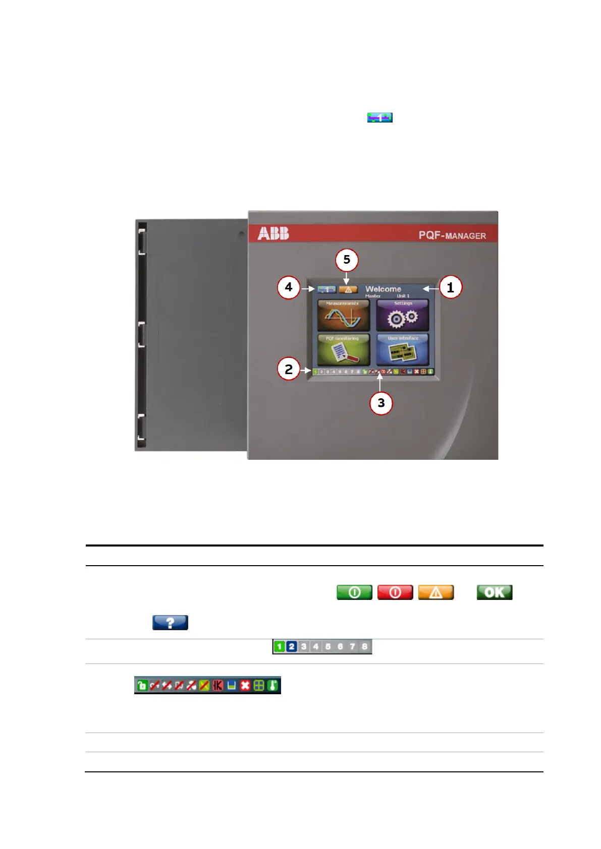
button is "deactivated" on the slave Managers. Figure 12 shows the front side of the PQF-
Manager.
Figure 12: Front side of the PQF-Manager
Five main parts can be distinguished (see Table 6)
Table 6: Front side of the PQF-Manager
1
Menu display
By navigating through the menus with the , , and
buttons, the filter can be set-up and controlled
. On-line help is available by pressing
the button.
2
Master/slaves units monitor
3
Locking status / Alarm and fan contact indicator / Digital output contact indicator
When the PQF-Manager closes one of its output relays, the corresponding symbol
lights up. The digital outputs of the PQF-Manager are discussed later in this section.
4 Filter selection
Start stop acknowledgment fault