Manual Power Quality Filter PQFS The PQF-Manager user interface 75
Programmed alarm can:
− activate any digital output relay 1-6 if selected
− activate global alarm NO/NC relay
Tprobe alarm 1 to 8 can activate global alarm NO/NC relay.
Warnings
Programmed warning can activate any digital output relay 1-6 if selected.
Tprobe warning 1 to 8 can activate global fan NO relay.
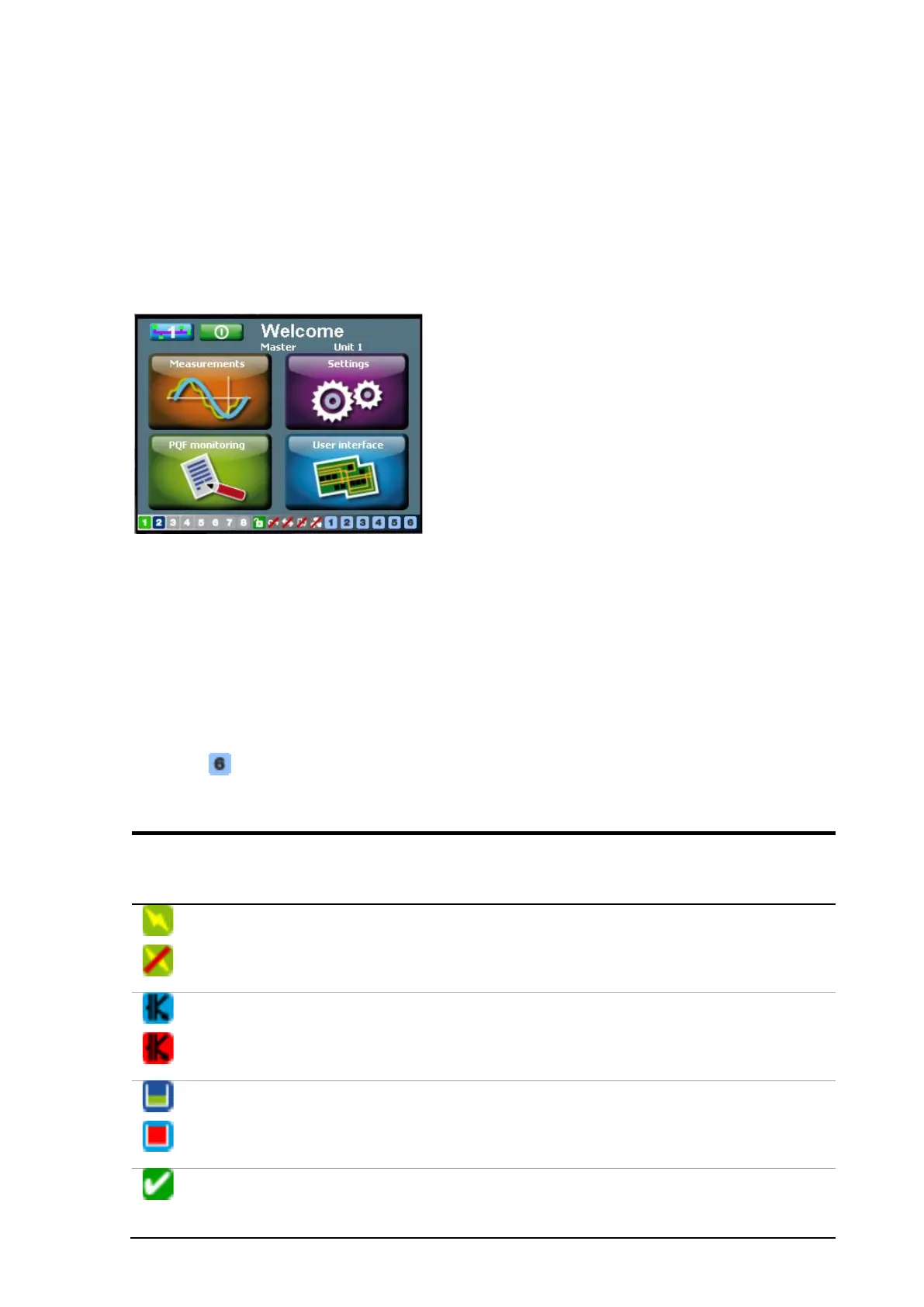
Digital output contact icons are located at the bottom of the screen (Cf. Figure 52).These
icons are numbered 1 to 6 when they are disabled. If these output contacts are
programmed, the corresponding icon changes. When the PQF-Manager closes one of its
six digital output relays (Cf. Chapter 6) the corresponding symbol changes its
appearance as described in the Table 35. When the relay considered opens again, the
symbol takes back the original appearance.
If a digital output is ‘Disabled’ the default icon is shown.
Example:
Table 35 Digital outputs status icons
setting for digital
output
Output relay closes when…
Auxil. OFF
The auxiliary power is present in the main filter enclosure
and the main controller is communicating with the PQF-
Manager
PQF running
PQF not running
The active filter is ‘on’ (IGBTs switching) or in ‘standby’
(main contactor closed but IGBTs not switching)
Full load
The active filter is running under full load condition
Armed
The filter is ON or is in the start-up procedure, or it is
stopped in fault condition but will restart as soon as the
fault has disappeared