Connection
Chapter 5
56
1SFC132003M0201
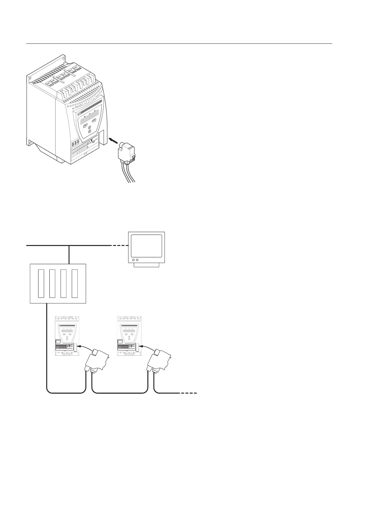
5:3 Connection of communication
devices (optional)
5:3.1 Fieldbus communication
The fieldbus communication plug shall be connected to the
communication interface on the front of the PST, see Figure
35.
Make sure that the plug is in correct position and tighten the
screw with 0.8 Nm (7.1 lb in) and additional 1/4 turn.
For programming and other information,
see Chapter 7 “Settings and configuration” and Chapter 8
“Fieldbus communication (option)” .
1L1
2T1
4T2
6T3
B1
B2
B3
3L2
5L3
1
100-250V
Stop
Start
In0
In1
Vc
AC/DC, 50/60 Hz
2
3
4
5
6
7
8
9
10
Vp
Vp
11
K4
12
13
14
Vn
15
16
K5
17
18
19
K6
20
LISTED 7F39
IND. CONT. EQ
.
1SFA 894 007 R1002
IEC 947-4-2
Ie: 37-72A
Us: 100-250V AC/DC
UL 508
Uc: 100-250V AC/DC
FLA: 37-68A
Made in Sweden
Ue: 220-230 380-400 500 V
72: AC-53a: 8-1.6: 80-6
In line 18,5 37 45 kW
Ue 208 220-240 440-480 V
PTC
Key-Pad
FELDBUSS
CAUTION
Fuse 250A TYPOWER ZILOX
Max short circuit current 65kA at 480V
Wire 1-8 Al Cu 75C only, 35lb-in
Overload Capacity 115% of Continuous
L
N
1SFC132066F0001
igure 35: Fieldbusplug
Made in Sweden
PTCKey-Pad Fieldbus
Made in Sweden
PTCKey-Pad Fieldbus
1SFC132067F0001
igure 36: Principle of a fieldbus network with PST softstarters connected
 Loading...