Synchronism and energizing
check for double circuit breakers
and voltage selection
ABB Network Partner AB
1MRK 580 167-XEN
Page 5 - 41
Version 1.0-00
These voltage inputs are used:
U-line UL1, UL2 or UL3 voltage input on the terminal.
U-bus U5 voltage input on the terminal
These MMI settings can be used during the test if the final setting is not
determined:
1 Set these MMI settings, which are found under:
Settings
Functions
Group n
SynchroCheck1
2 Test with UDiff = 0%
• Apply voltages U-line (UL1) = 80% U
r
/sqr3 and U-Bus (U5) = 80%
U
r
/sqr3.
• Check that the SYN1-AUTOOK and SYN1-MANOK outputs are
activated.
• The test can be repeated with different voltage values to verify that
the function operates within UDiff <30%.
3 Test with UDiff = 40%
• Increase the U-bus (U5) to 120% U
r
/sqr3, and the U-line (UL1) = 80%
U
r
/sqr3.
• Check that the two outputs are not activated.
4 Test with UDiff = 20%, Uline < UHigh
• Decrease the U-line (UL1) to 60% U
r
/sqr3 and the U-bus (U5) to be
equal to 80% U
r
/sqr3.
• Check that the two outputs are not activated.
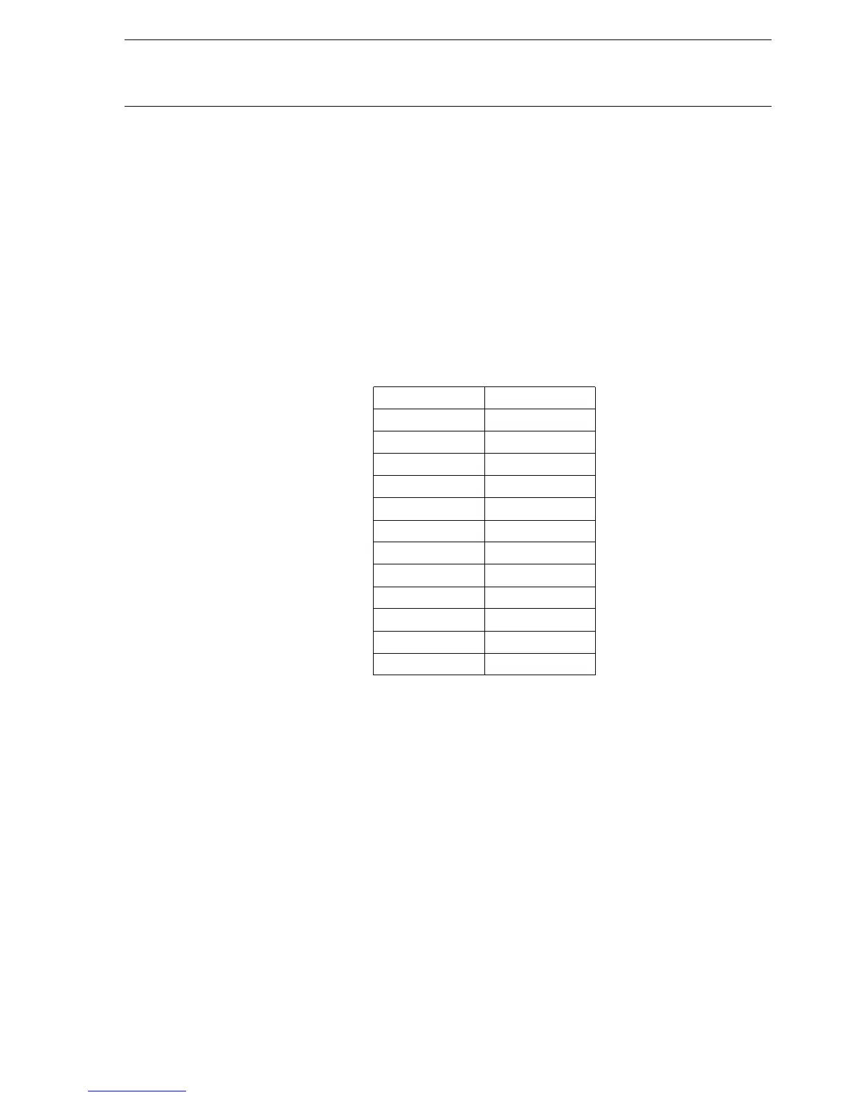
Parameter Setting
Operation On
InputPhase UL1
USelection SingleBus
AutoEnerg Off
ManEnerg Off
UHigh 70%
Ur/sqr3
ULow 40% Ur/sqr3
FreqDiff 0.05 Hz
PhaseDiff 45°
UDiff 30%
tAutoEnerg 0.5 s
tManEnerg 0.5 s