EQUATION1201 V3 EN-US (Equation 115)
The current setting for step 1 is chosen as the largest of the above calculated
residual currents, measured by the protection.
Step 2
M15282-144 v7
This step has directional function and a short time delay, often about 0.4 s. Step 2
shall securely detect all earth faults on the line, not detected by step 1.
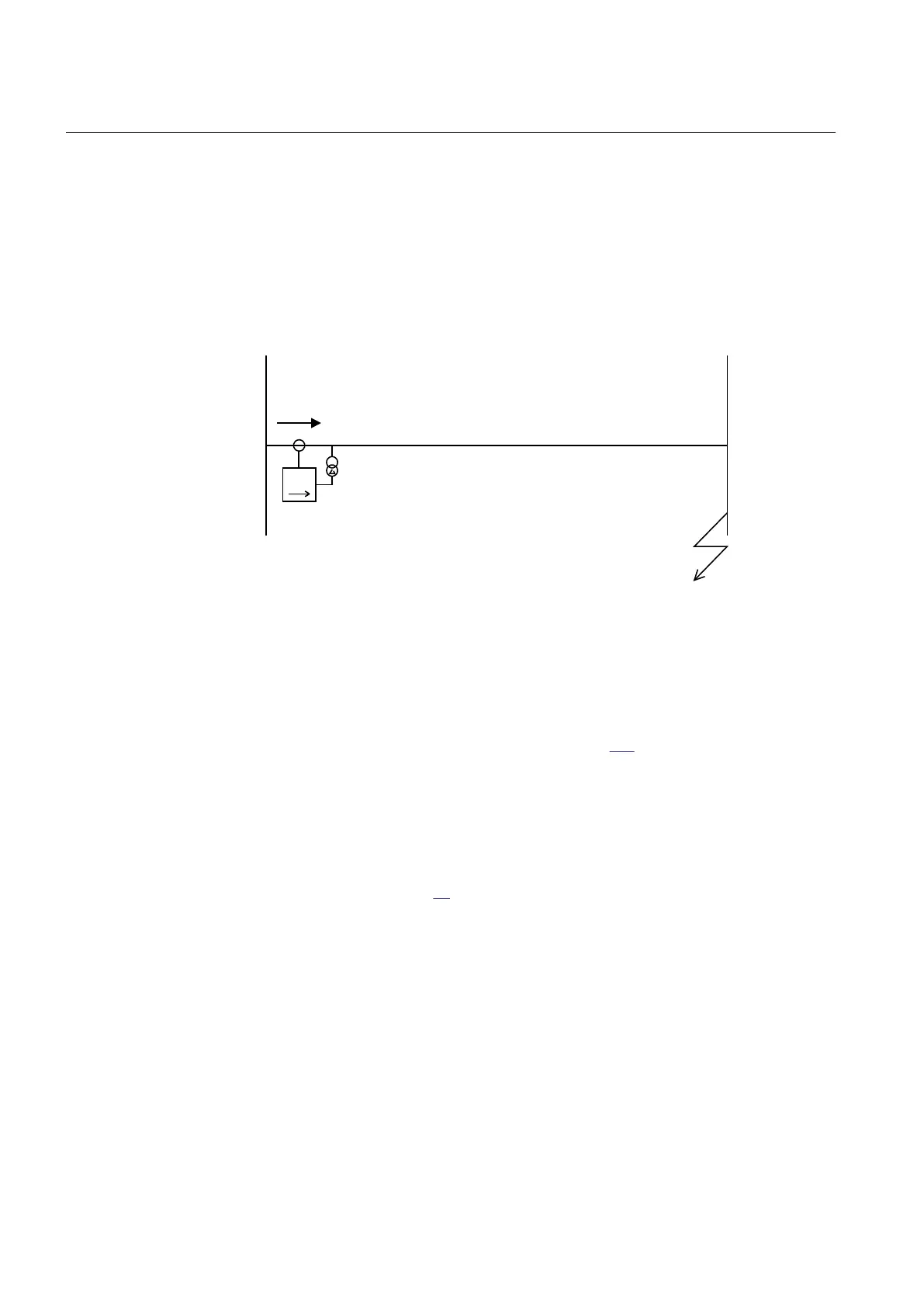
IN
>
One- or two-phase earth-fault
3I
0
IEC05000154-en-2.vsd
IEC05000154 V2 EN-US
Figure 88: Step 2, check of reach calculation
The residual current, out on the line, is calculated at an operational case with
minimal earth-fault current. The requirement that the whole line shall be covered
by step 2 can be formulated according to equation 116.
step2 0
I 0.7 3I (at remote busbar)³ ×
EQUATION1202 V4 EN-US (Equation 116)
To assure selectivity the current setting must be chosen so that step 2 does not
operate at step 2 for faults on the next line from the remote substation. Consider a
fault as shown in Figure
89.
Section 8 1MRK 505 393-UEN B
Current protection
178 Line differential protection RED650 2.2 IEC
Application manual

 Loading...


