IN
>
One phase-to-earth
fault
3I
0
IN
>
3I
01
IEC05000155-en-2.vsd
IEC05000155 V3 EN-US
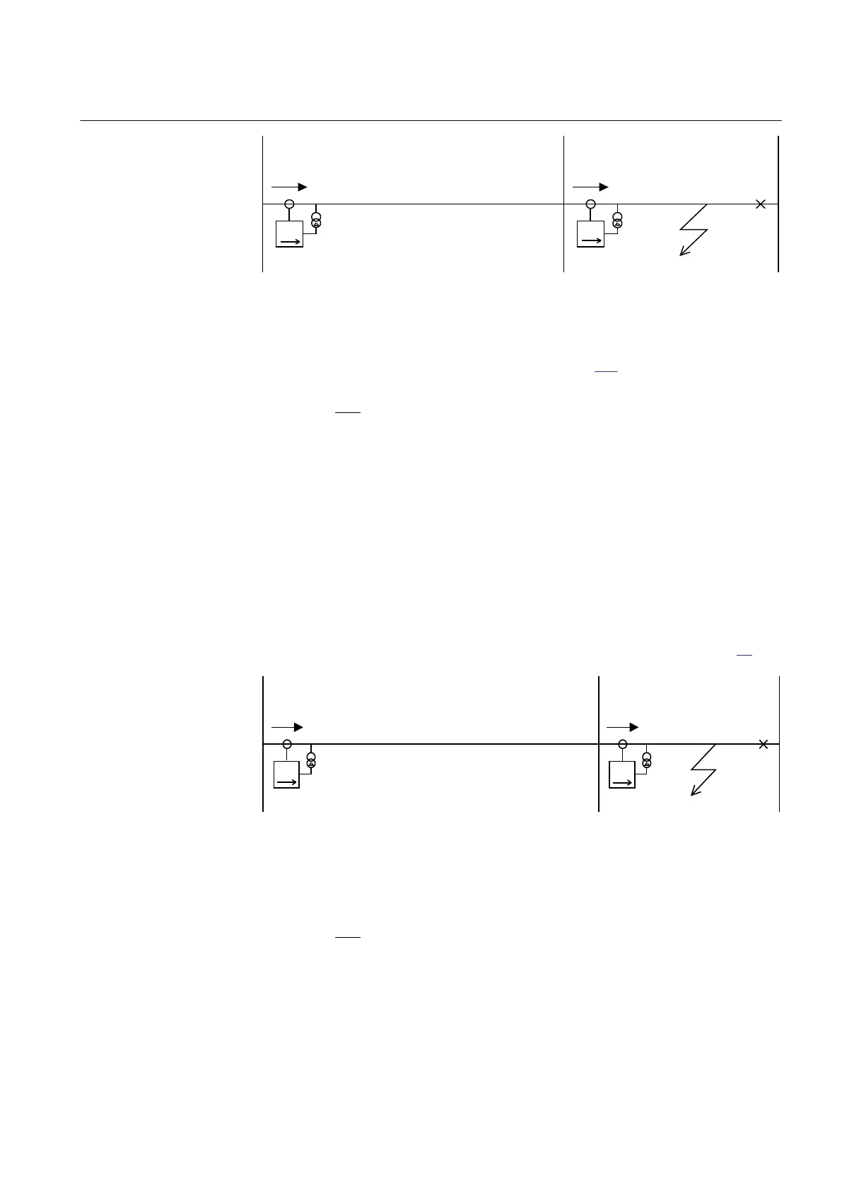
Figure 89: Step 2, selectivity calculation
A second criterion for step 2 is according to equation 117.
1
1
0
step2 step1
0
3I
I .2 I
3I
³ × ×
EQUATION1203 V4 EN-US (Equation 117)
where:
I
step1
is the current setting for step 1 on the faulted line.
Step 3
M15282-164 v6
This step has directional function and a time delay slightly larger than step 2, often
0.8 s. Step 3 shall enable selective trip of earth faults having higher fault resistance
to earth, compared to step 2. The requirement on step 3 is selectivity to other earth-
fault protections in the network. One criterion for setting is shown in Figure 90.
IEC05000156-3-en.vsd
IN
>
One phase-to-
earth fault
3I
0
IN
>
3I
02
IEC05000156 V3 EN-US
Figure 90: Step 3, Selectivity calculation
1
0
step3 step2
02
3I
I .2 I
3I
³ × ×
EQUATION1204 V4 EN-US (Equation 118)
where:
I
step2
is the chosen current setting for step 2 on the faulted line.
1MRK 505 393-UEN B Section 8
Current protection
Line differential protection RED650 2.2 IEC 179
Application manual

 Loading...


