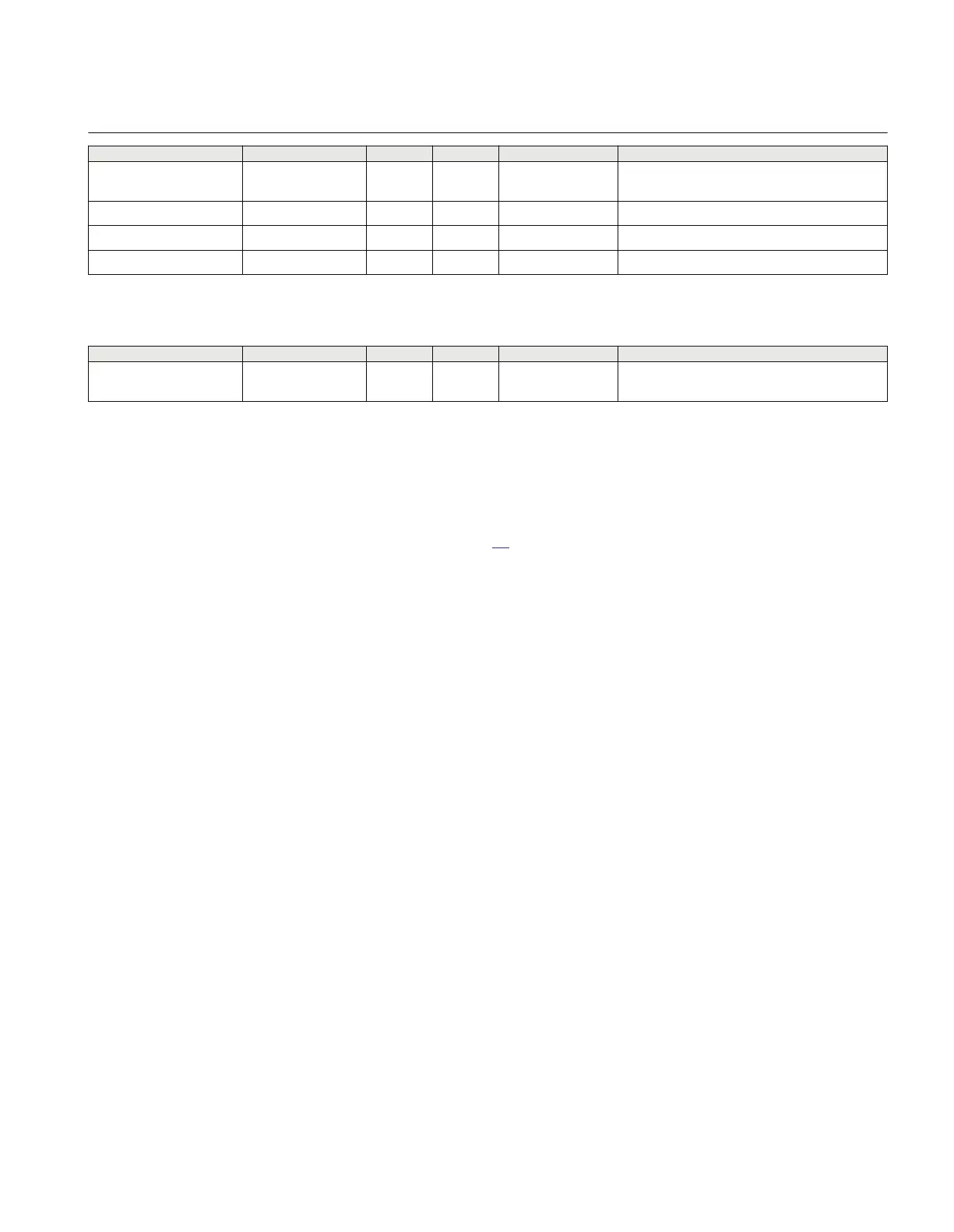
Name Values (Range) Unit Step Default Description
UVPickup 1 - 100 %VB 1 70 Voltage level for detection of dead line in % of
VBase
tDuration 0.000 - 60.000 s 0.001 0.020 Time delay for UI detection
tSOTF 0.000 - 60.000 s 0.001 1.000 Drop off delay time of switch onto fault function
tDLD 0.000 - 60.000 s 0.001 0.200 Delay time for activation of dead line detection
Table 69: ZCVPSOF Non group settings (basic)
Name Values (Range) Unit Step Default Description
GlobalBaseSel 1 - 6 - 1 1 Selection of one of the Global Base Value
groups
6.8.6 Operation principle
Automatic switch onto fault logic, voltage and current based function (ZCVPSOF) can be
activated externally by Breaker Closed Input or internally (automatically) by using VI
Level Based Logic see figure 87.
The activation from the Dead line detection function is released if the internal signal
deadLine from the VILevel function is activated at the same time as the input ZACC is not
activated during at least for a duration tDLD and the setting parameter AutoInit is set to
Enabled.
When the setting AutoInit is Disabled, the function is activated by an external binary input
BC. To get a trip one of the following operation modes must also be selected by the
parameter Mode:
Mode = Impedance; trip is released if the input ZACC is activated (normal connected to
non directional distance protection zone).
Mode = VILevel; trip is released if VILevel detector is activated.
Mode = VILvl&Imp; trip is initiated based on impedance measured criteria or VILevel
detection.
The internal signal deadLine from the VILevel detector is activated if all three phase
currents and voltages are below the setting IPhPickup and UVPickup.
VI Level based measurement detects the switch onto fault condition even though the
voltage is very low. The logic is based on current and voltage levels. The internal signal
SOTF VILevel is activated if a phase voltage is below the setting UVPickup and
corresponding phase current is above the setting IPhPickup longer than the time
tDuration.
1MRK 506 335-UUS A Section 6
Impedance protection
185
Technical manual





 To Next Page