12.1.5 Settings
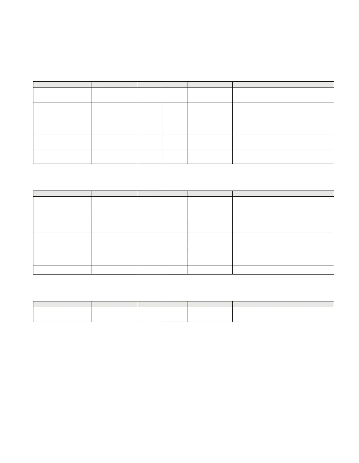
Table 333: ZCPSCH (85) Group settings (basic)
Name
Values (Range) Unit Step Default Description
Operation Disabled
Enabled
- - Disabled Disable/Enable Operation
SchemeType Intertrip
Permissive UR
Permissive OR
Blocking
DeltaBlocking
-
- Permissive UR Scheme type
tCoord 0.000 - 60.000 s 0.001 0.035 Communication scheme channel coordination
time
tSendMin 0.000 - 60.000 s 0.001 0.100 Minimum duration of a carrier send signal
(carrier continuation)
Table 334: ZCPSCH (85) Group settings (advanced)
Name Values (Range) Unit Step Default Description
Unblock Disabled
NoRestart
Restart
-
- Disabled Operation mode of unblocking logic
DeltaI 0 - 200 %IB 1 10 Current change level in % of IB for fault
inception detection
DeltaV 0 - 100 %VB 1 5 Voltage change level in % of UB for fault
inception detection
Delta3I0 0 - 200 %IB 1 10 Zero seq current change level in % of IB
Delta3V0 0 - 100 %VB 1 5 Zero seq voltage change level in % of UB
tSecurity 0.000 - 60.000 s 0.001 0.035 Security timer for loss of carrier guard detection
Table 335: ZCPSCH (85) Non group settings (advanced)
Name
Values (Range) Unit Step Default Description
GlobalBaseSelector 1 - 6 - 1 1 Selection of one of the Global Base Value
groups
12.1.6 Operation principle
Depending on whether a reverse or forward directed impedance zone is used to issue the
send signal, the communication schemes are divided into Blocking and Permissive
schemes, respectively.
A permissive scheme is inherently faster and has better security against false tripping than
a blocking scheme. On the other hand, a permissive scheme depends on a received signal
1MRK 506 335-UUS A Section 12
Scheme communication
497
Technical manual





 To Next Page