E-OCD II Debugger User’s Manual E-OCD II Interface Hardware
Two LEDs for ‘Power’ and ‘Debug Run’
Not support hot plugging
Note : The target system must not be powered during insertion or release of the OCD interface
2.1.2 E-OCD H/W Connection
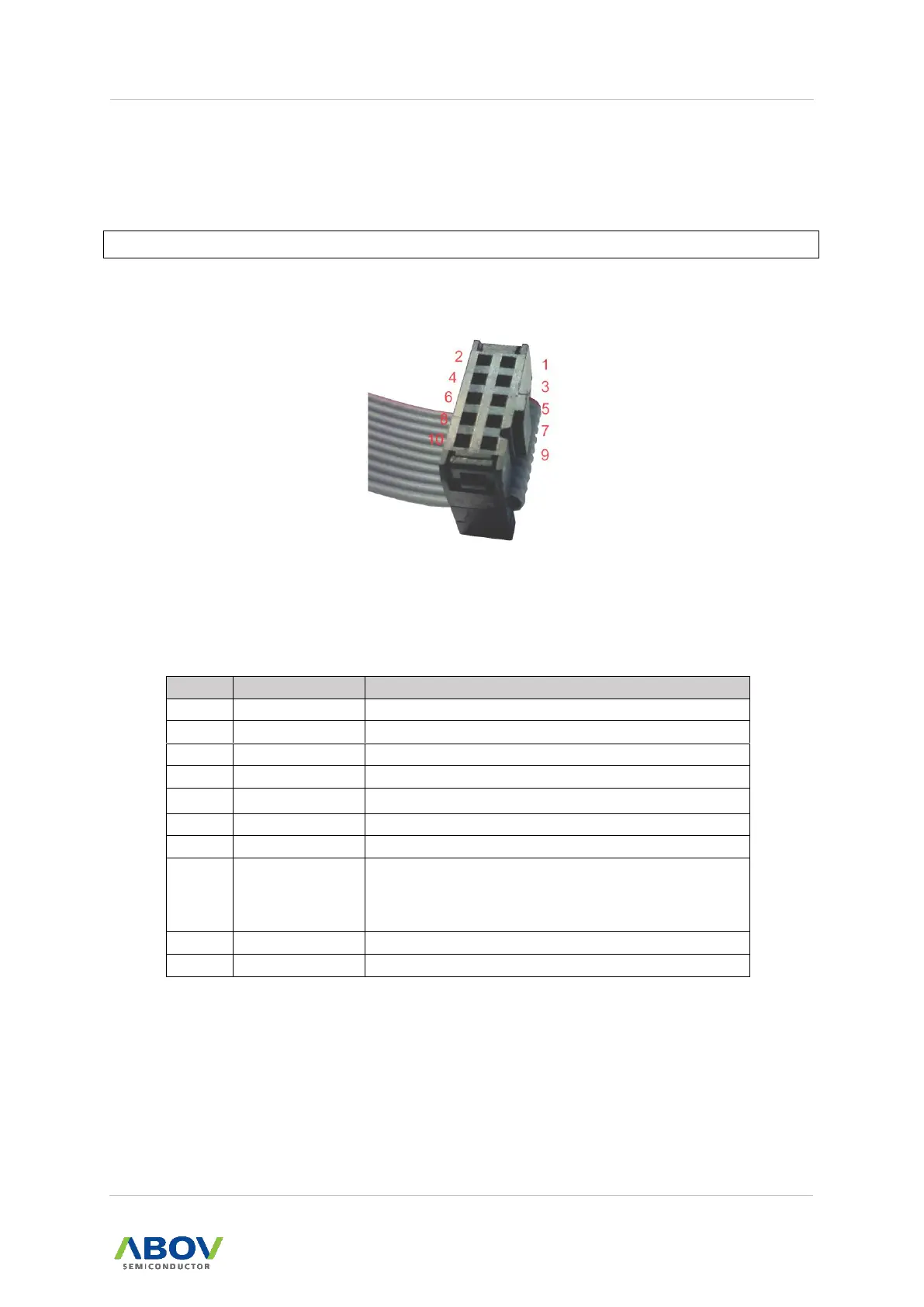
Figure 2-1 Cable Side View
Table 2-1 Pin Assignment
Detects the target system’s power and interface voltage level.
Connect RunFlag pin of 94/97series Device.
Serial clock of the OCD interface.
Serial data of the OCD interface.
If the target system’s output is very noisy, it is
recommended to add a small capacitance to this line.

 Loading...