42
15.4 SPEED POT AND PRESET SPEED CONTROL
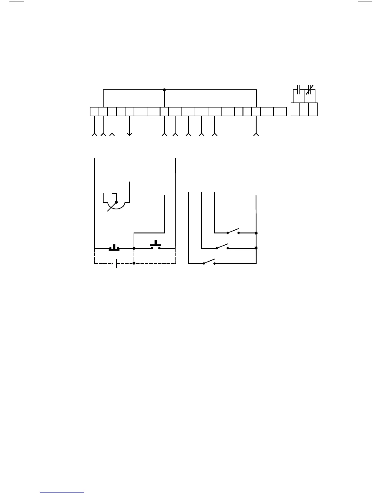
Shown below is the wiring diagram for a control scheme that utilizes a speed pot
and PRESET SPEEDS for speed control, and either a two-wire or three-wire
START/STOP circuit:
NOTES:
1. Program the PRESET SPEEDS (Parameters 1-4) to the desired values.
2. Program TB-13A to select SPEED #1, TB-13B to select SPEED #2, and TB-
13C to select SPEED #3 (refer to Parameters 47, 48, and 49).
3. To select a preset speed, close the appropriate terminal to TB-2. To select
SPEED #4, close any two of the preset speed terminals to TB-2.
4. Speed pot control can be selected by one of two methods. If none of the preset
speeds are selected (all TB-13 terminals are open), the drive will default to
speed pot control if Parameter 29 - MANUAL is set to 0-10 VDC. The speed
pot can also be selected if one of the TB-13 terminals is programmed to select
0-10 VDC and that terminal is closed to TB-2.
5. If REVERSE rotation is required, TB-13C cannot be used to select SPEED #3.
TB-13C must be programmed to select RUN REVERSE or START REVERSE,
leaving only TB-13A and TB-13B to select preset speeds.
CIRCUIT COMMON
PRESET SPEED #1
START
CIRCUIT COMMON
10 VDC SUPPLY
0-10 VDC INPUT
CIRCUIT COMMON
STOP
1 2 5A 5B 6 10A 12A RXA TXB10B 2 13A 13B 13C 13D 14 15 2
16 17 18
PRESET SPEED #2
PRESET SPEED #3
SPEED POT
(10 K)