39
15.0 MC1000 CONTROL WIRING DIAGRAMS
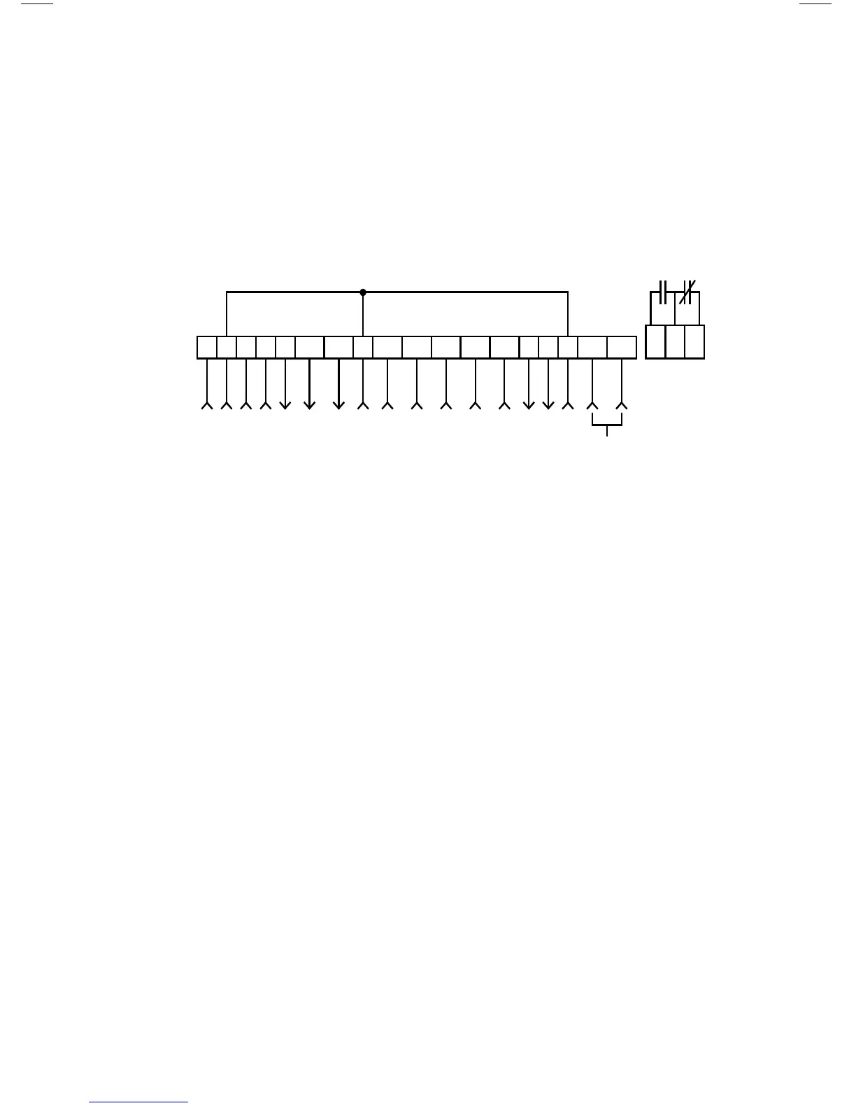
15.1 MC1000 TERMINAL STRIP
Shown below is the terminal strip on the main control board, along with a brief
description of the function of each terminal. Wiring shown above the terminal
strip indicates internal wiring on the main control board.
NOTE: The function of terminals TB-10A, TB-10B, TB-13A, TB-13B, TB-
13C, TB-13D, TB-14, TB-15, TB-16, and TB-18 are dependent on the programming
of certain parameters. In most cases, the name of the parameter matches the
number of the terminal, allowing quick and easy programming of the terminals to
suit the application. The exception is TB-16 and TB-18, which are governed by
Parameter 54 - RELAY.
A complete description of operating the drive in the REMOTE mode can be found
in Section 14.2. The following diagrams provide a quick reference to wire the drive
for the most common configurations.
1 2 5A 5B 6 10A 12A RXA TXB
FORM C
RELAY
10B 2 13A 13B 13C 13D 14 15 2
16 17 18
STOP
CIRCUIT COMMON
0-10 VDC SPEED REFERENCE INPUT
10 VDC SUPPLY FOR SPEED POT
0-10 OR 2-10 VDC OUTPUT: FREQUENCY
0-10 OR 2-10 VDC OUTPUT: LOAD
CIRCUIT COMMON
START
TB-13A FUNCTION SELECT
TB-13B FUNCTION SELECT
TB-13C FUNCTION SELECT
TB-13D FUNCTION SELECT
OPEN-COLLECTOR OUTPUT
OPEN-COLLECTOR OUTPUT
RS-485 SERIAL
COMMUNICATIONS
CIRCUIT COMMON
4-20 mA SPEED REFERENCE INPUT