56
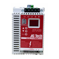
FREQUENCY (Hz)
MAXIMUM CONTINUOUS
OUTPUT CURRENT (%)
NON-COMPENSATED
SPEED COMPENSATED
10 20 30 40 50 60
20
40
60
80
100
NOTE 1: The above diagram is based on a MOTOR OL setting of 100%. For
lower MOTOR OL settings, reduce the % CURRENT values by the same
percentage. For example, if MOTOR OL is set to 75%, reduce the % CURRENT
values by 25%. Therefore, the curve shifts down, but the shape of the curve
remains the same.
The “non-compensated” thermal overload circuit allows 100% current
continuously, and 150% current for one minute, at all speeds. In the example
above, the motor operating at 10 Hz without “speed-compensated” protection
would be allowed to operate continuously at 27 Amps, and could draw 40.5
Amps for one minute before tripping. Without sufficient motor cooling, this can
result in motor failure due to overheating.
The “non-compensated” circuit is selected by setting Parameter 22 - TORQUE to
CT/NOCMP. The “non-compensated” setting should only be used in applications
where the motor is properly cooled at all speeds, or the motor manufacturer has
approved the motor for full-load operation at low speeds.
NOTE 2: The operation of the motor thermal overload circuit is affected by the
setting of Parameter 34 - LOAD MLT.
18 BASE (BASE FREQUENCY)
The BASE FREQUENCY determines the V/Hz ratio by setting the frequency at
which the drive will output full voltage to the motor. For most applications the
base frequency should be set to match the motor’s rated frequency.
 Loading...