A
C Tech
Variable Speed AC Motor Drives
A
C Tech ! 660 Douglas St. ! Uxbridge, MA 01569 ! Ph: (800)217-9100 ! Ph: (508)278-9100 ! Fax: (508) 278-7873
MC SERIES DYNAMIC BRAKING and ADDITIONAL FORM C RELAY OPTION
INSTALLATION INSTRUCTIONS
Manual Number: IMMDBA01
These instructions apply to MC models rated: 0.5 - 5 HP, 240/200 Vac
1 - 7.5 HP, 480/400 Vac
1 - 7.5 HP, 590/480 Vac
1.0 GENERAL
These installation instructions apply to the Dynamic Braking and Additional Form C Relay options available for the MC Series
variable frequency drives. These components can also be ordered with the drive as factory installed options. Refer to the MC
Series Product Catalog for more information.
The exploded diagram (DIAGRAM A) in this document shows the Dynamic Braking Option Board for illustration purposes.
The Additional Form C Relay Option Board is very similar, and the installation procedure is the same.
2.0 DYNAMIC BRAKING
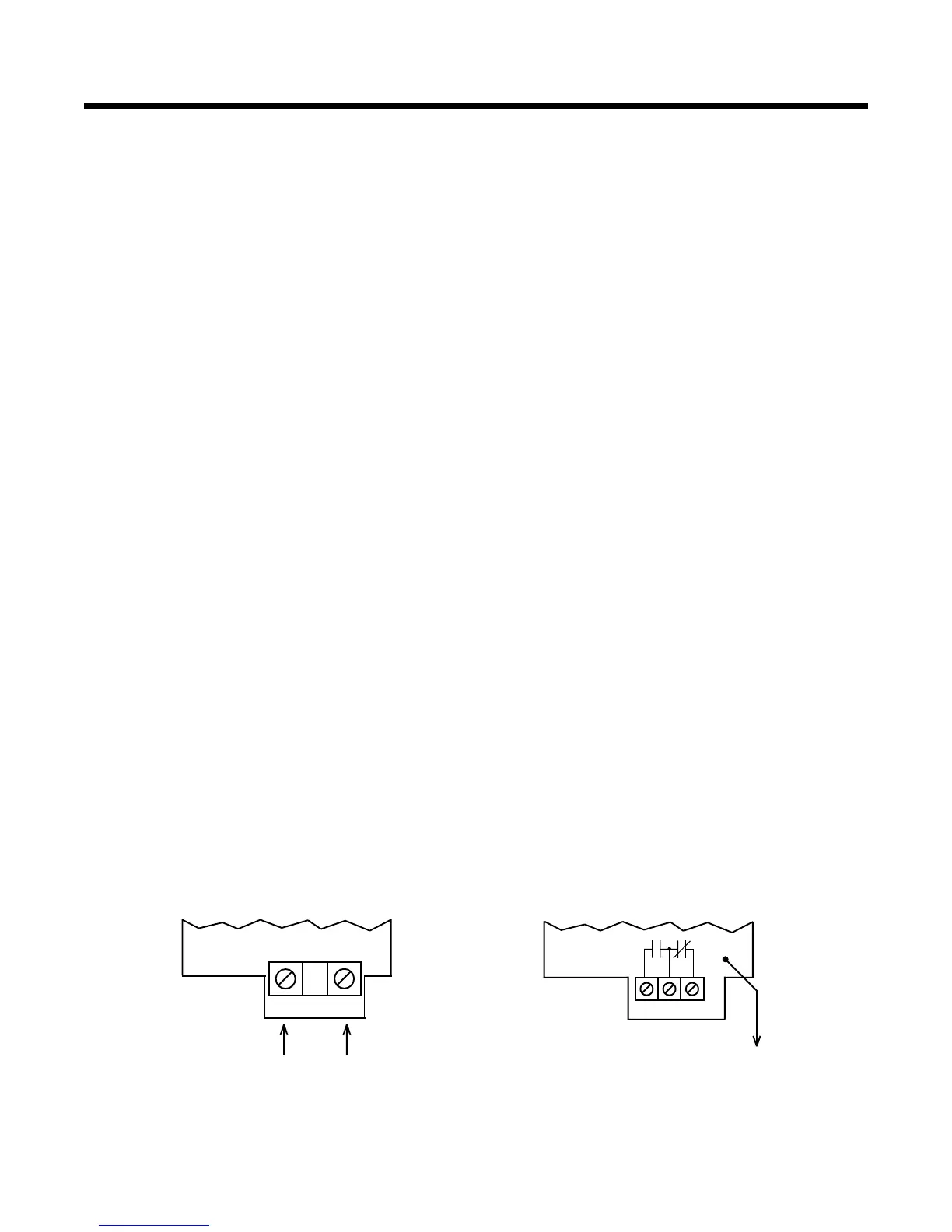
The Dynamic Braking Option includes a resistor assembly that is mounted externally from the drive. The two wires (RED and
BLUE) from the resistor assembly are connected to DB1 and DB2 on the DB Board, as shown in the diagram below.
In order to activate the Dynamic Braking feature, Parameter 14 - DYN BRAKE must be set to ON. Refer to the MC1000 or
MC3000 Series Installation and Operation Manual for information on programming the drive.
NOTE (For 240 Vac drives only): If the Dynamic Braking kit was ordered separately from the drive, refer to DIAGRAM B for
resistor assembly modifications. Resistor assemblies supplied with DB kits that are ordered separately are shipped in the 480
Vac and 590 Vac configuration, and must be modified to operate with 240 Vac drives.
3.0 ADDITIONAL FORM C RELAY
The Additional Form C Relay Board converts one of the two open-collector outputs on the Main Control Board into a Form C
relay output, resulting in two Form C relays and one open-collector output being available for drive status indication. This is
done by connecting the yellow wire from the Relay Board to terminal 14 on the Main Control Board, and then programming
Parameter 52 - TB14 OUT for the desired indication. Refer to the MC1000 or MC3000 Installation and Operation Manual for
information on programming the drive.
The Relay Board has a terminal block labeled 19, 20, and 21, which are the contacts of the Form C relay. The configuration is
the same as the Form C relay at terminals 16, 17, and 18 on the Main Control Board, and is shown below.
DB1 DB2
19
20 21
YELLOW WIRE
To TB-14 on Main
Control Board
RED
WIRE
BLUE
WIRE
From Resistor Assembly
Dynamic Braking Board
Relay Board