www.accuenergy.com
V: 1.0 Revised: Jan. 2018
Chapter 3: Installation - Conguration Parameter Set-up
25
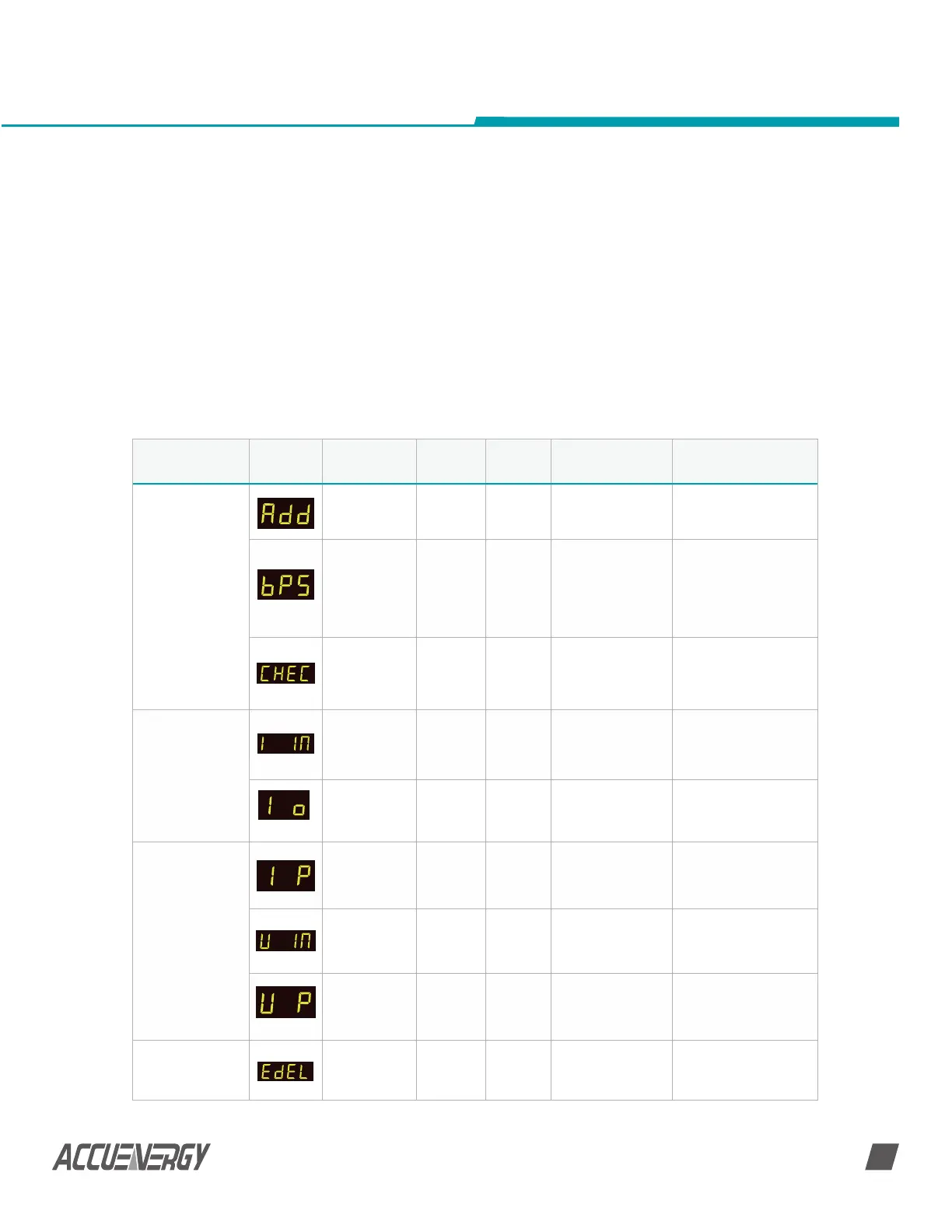
Label Paramters Default Options Description Note
Communication
parameter setup
Communica-
tion address
1 1 ~ 247
The address can
be any integer
between 1~247
Assign different ad-
dresses to meters on
same bus
Baud Rate 19200
1200;
2400;
4800;
9600;
19200;
38400
Data Transmission
Rate
All devices on the
same communica-
tion bus must use the
same baud rate
Parity Non1
even;
odd;
non1;
non2
All devices on the
same communica-
tion bus must use the
same parity
Shunt/Hall Effect
Sensor Parameter
Setup
Current input
of the shunt
/ hall effect
sensor
20
20 ~
50000A
Only indirect current
measurement has this
screen
Current
output of the
shunt
100
50 ~
100mV
Corresponds to the
output range of the
shunt
Hall Effect Sensor
Setup
output range
of the current
Hall Effect
Sensor
0 0; 1
0: 4~20mA/0~±5V
1:
4~12-20mA/0~±4V
rated voltage
of the Voltage
Hall Effect
Sensor
0 ~ 3000V
Only meter with indi-
rect voltage measure-
ment has this screen.
output range
of the voltage
Hall Effect
Sensor
0 0; 1
0: 0 ~ ±5V;
1: 0 ~ ±4V
Energy, Ah and
DI counter clear
setup
Energy
delete(energy
clear)
NO
NO;
Yes
No: energy not
cleared;
Yes: clear energy
to 0
3.2 General Parameter Setup
Press ‘F’ and ‘V/A’ simultaneously whiles in the metering display mode to get to the
system parameter setting mode. In parameter setting mode, pressing ‘F’ and ‘V/A’
simultaneously will exit the system parameter setting mode and return to the metering
data mode.
General parameter setup will define the general operating characteristics, such as current
range setting, shunt current output range setting, rated voltage of voltage Hall Effect
sensor, reset energy, Ah and DI counter, meter clock setting, and password reset etc., as
shown in table 3-2.
NOTE: Some of these settings will vary depending on the model number and firmware
version of the meter.
 Loading...


