Machine Maintenance 3-75
3. Secure the ODD module to the bracket using two screws.
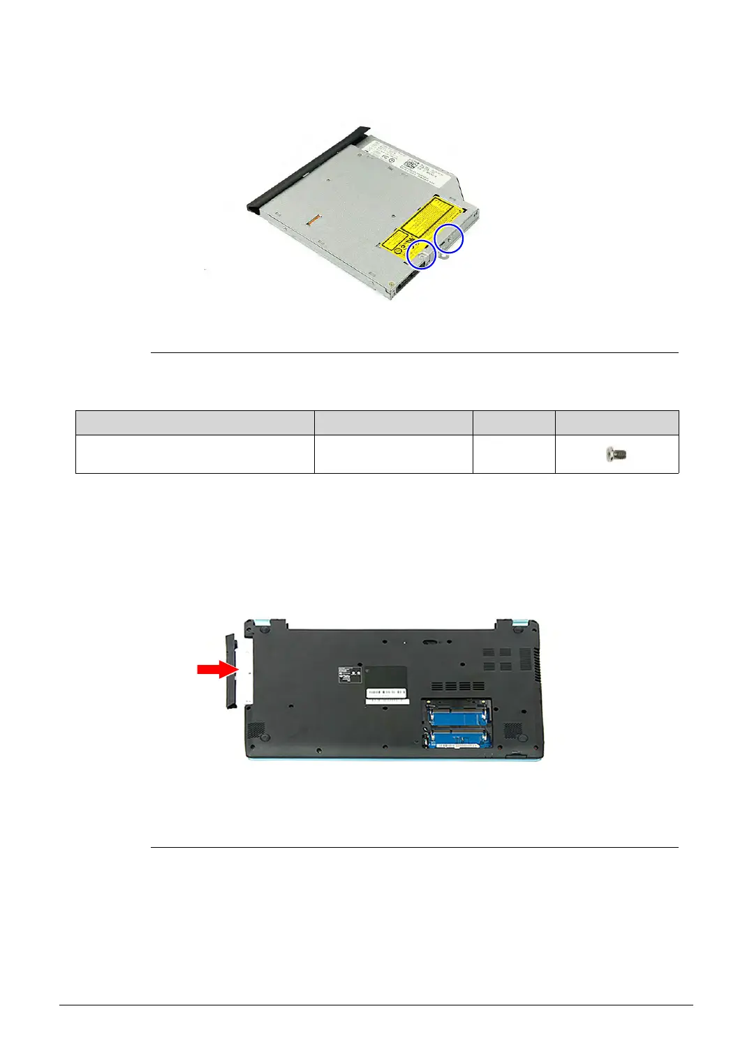
Figure 3-111. ODD Bracket Screws
4. Gently push the ODD module into the ODD drive bay until the ODD connector latch into
place.
Figure 3-112. ODD Module
5. Turn the computer over and open the LCD panel.
6. Secure the ODD module to the upper case assembly using one screw.
Table 3-111. Screws
Step Screw Quantity Screw Type
ODD Bracket Reassembly M2 × L3 2
http://mycomp.su/ - Maintenance and Service Guide,Service Manual,Motherboard Schematics for Laptop/notebook
РЕМОНТ НОУТБУКОВ. Запчасти и комплектующие для ноутбука. Схемы, сервис мануалы, инструкции по разборке ноутбука.
ВОССТАНОВЛЕНИЕ ДАННЫХ. г. Санкт-Петербург, Тел.(812)951-37-99, Тел.8-921-951-37-99,ICQ:573812745, service@it-lux.ru
 Loading...