Machine Maintenance 3-19
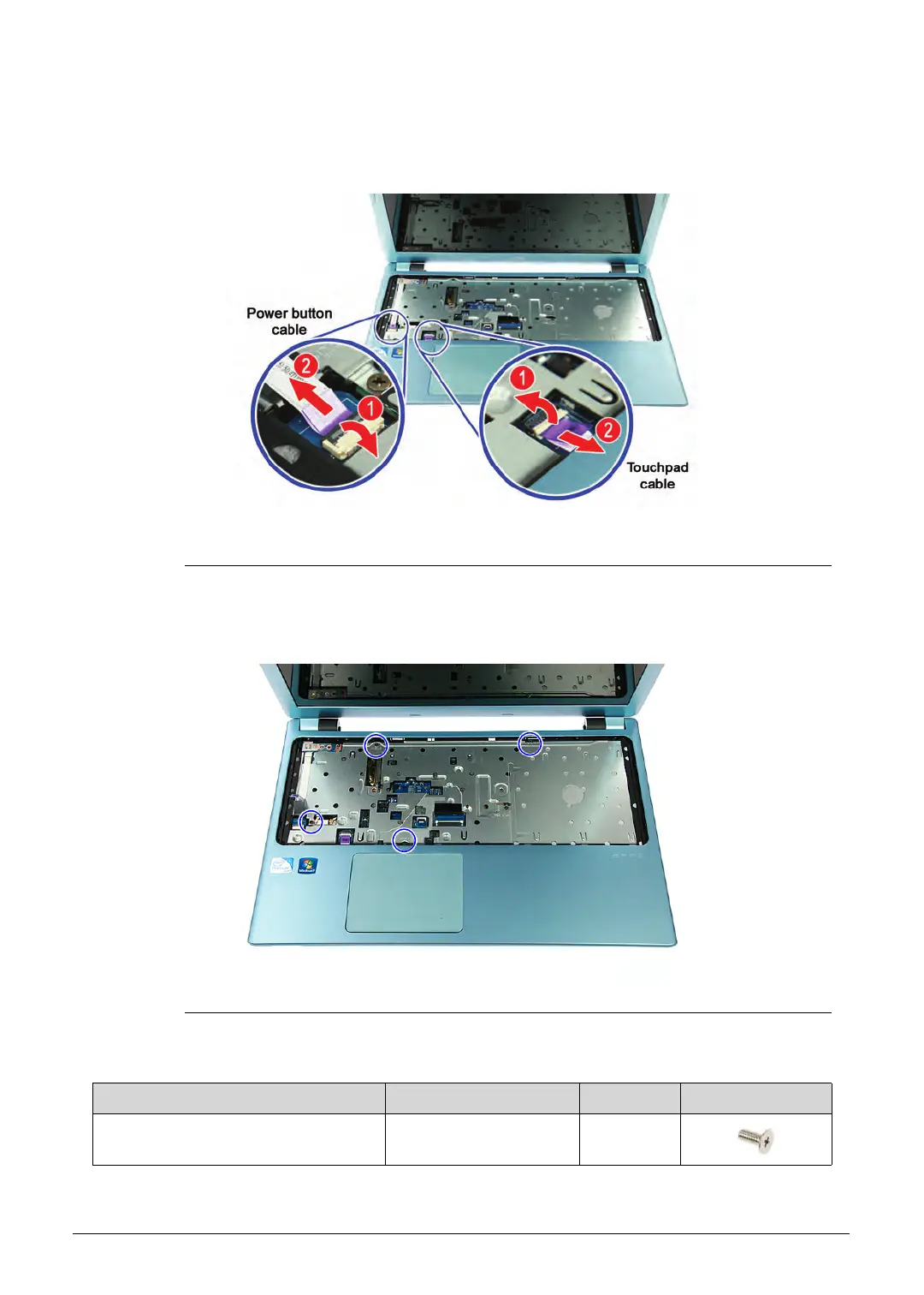
4. Release the connector latches from the mainboard (1), then disconnect the power button
and touchpad cables (2).
Figure 3-17. Power Button and Touchpad Cables
5. Remove the four screws securing the upper case to the lower case assembly.
Figure 3-18. Upper Case Screws – Top Side
Table 3-18. Screws
Step Screw Quantity Screw Type
Upper Case Disassembly M2.5 × L5 4
http://mycomp.su/ - Maintenance and Service Guide,Service Manual,Motherboard Schematics for Laptop/notebook
РЕМОНТ НОУТБУКОВ. Запчасти и комплектующие для ноутбука. Схемы, сервис мануалы, инструкции по разборке ноутбука.
ВОССТАНОВЛЕНИЕ ДАННЫХ. г. Санкт-Петербург, Тел.(812)951-37-99, Тел.8-921-951-37-99,ICQ:573812745, service@it-lux.ru