Condential
2-6
H6500
Item
Male Connector
on Main Board
The key feature Figure
A IR (J6)
Compose of Red/Black/Yellow
wire, Red connector and Black
wire tube (3 pin)
B Photo sensor (J16)
Compose of White/Black/Red
wire, Green connector and Gray
wire tube (3 pin)
C Blower (J8)
Compose of Red/White/Black
wire, White connector and Blue
wire tube (3 pin)
D System Fan (J9)
Compose of Red/Yellow/Black
wire, White connector (3 pin)
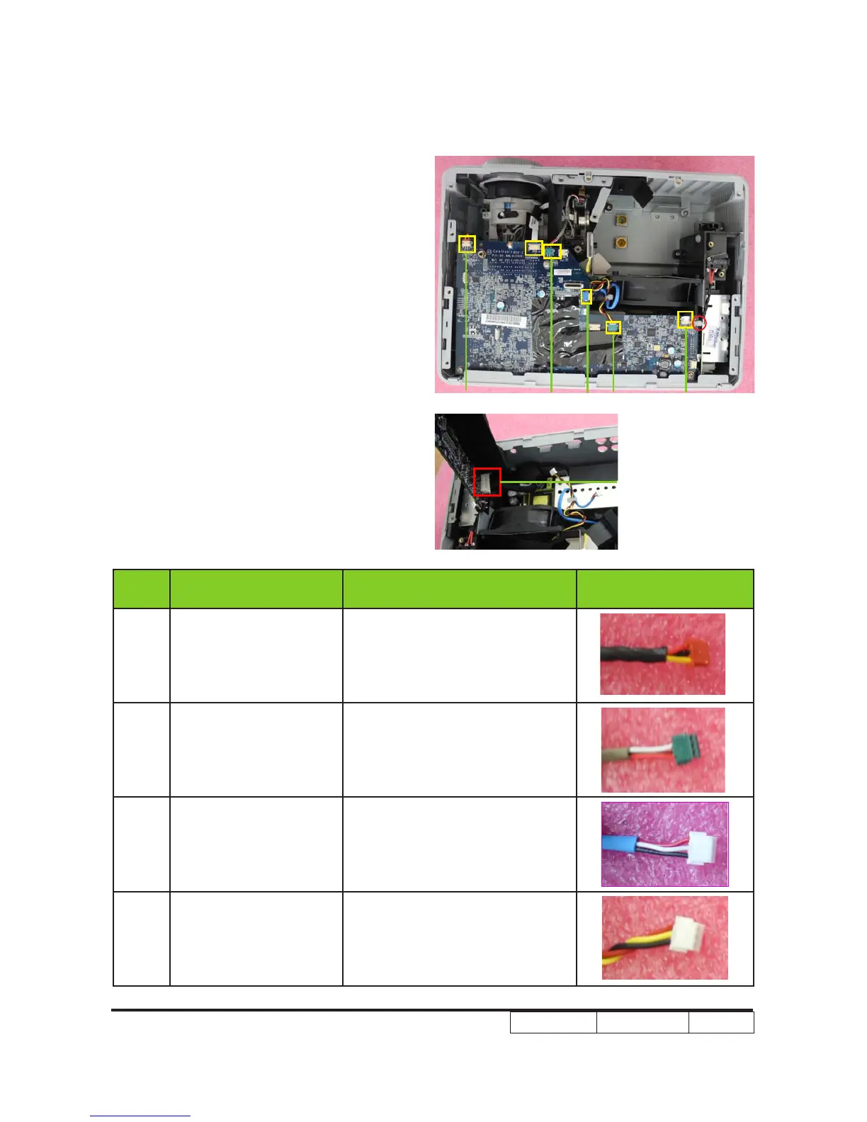
5. Unplug 6 connectors (as yellow square).Unplug 6 connectors (as yellow square).
6. Unplug 1 connector (as red square).Unplug 1 connector (as red square).
Please refer to the table as below for
details about each connector.
A
E
D
C
B
F