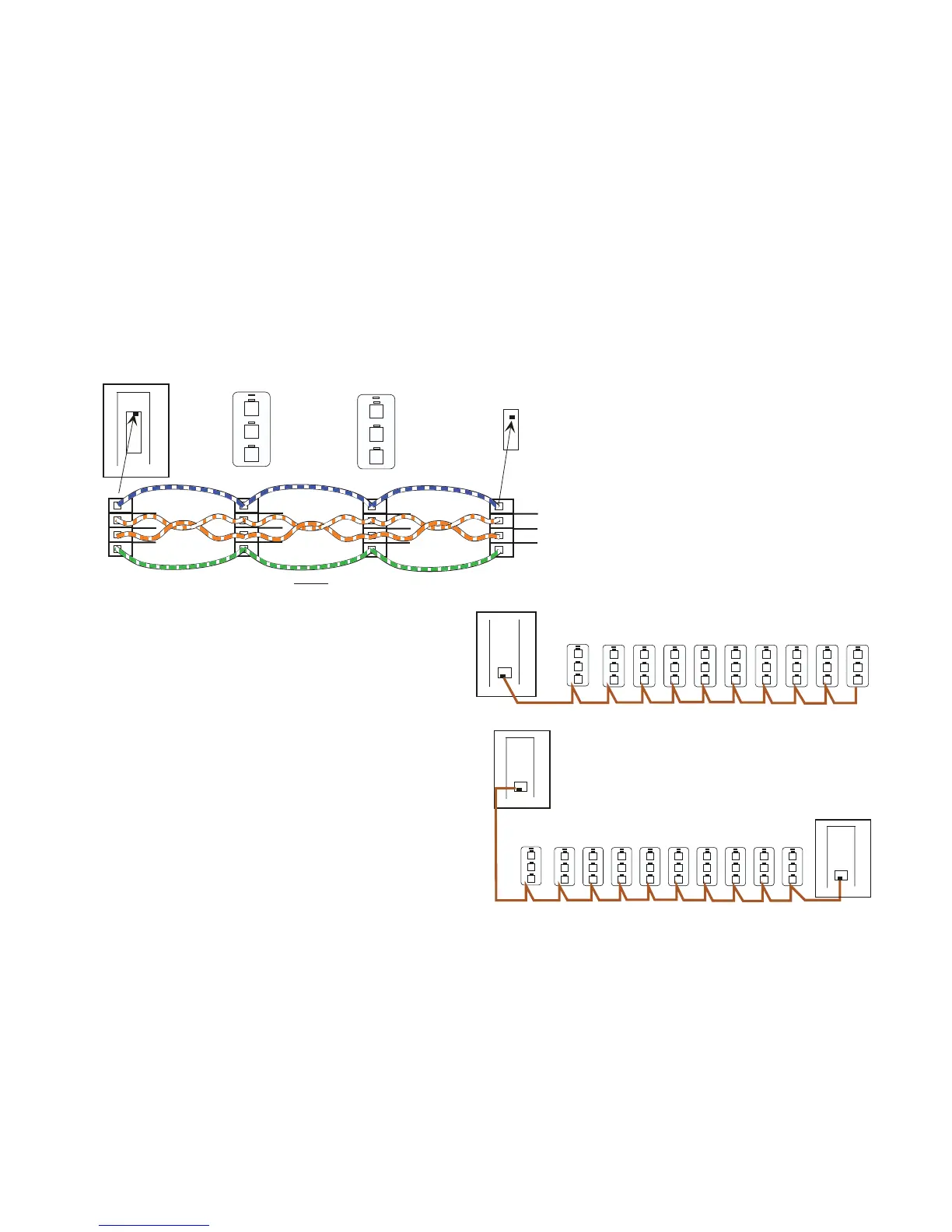
Single Panel with 10 switches will be OK with a wire length
of up to 200ft.
Panel A LCP 1
GND
+12V
DC
AB
4
3
2
1
GND
+12V
DC
4
3
2
1
AB
4
3
2
1
GND
+12V
DC
AB
GND
AB
+12V
DC
4
3
2
1
Blue W hite Pair
Orange/White
White/Orange
Panel A LCP 1
Switch 1
Switch 2
Panel B LCP 2
GR 2404 -DIM
Typical Hook up of a 2 Panel system with two Switches using
“1234" Connectors:
Panel A LCP 1
A panel at each end of the run increases the number of
switches and length of wire.
Panel B LCP 2
Switches with Long Distances Between Them and Multiple
Switches with only One Panel.
Cat 5 cable is 24 AWG and will carry 1 amp of current over 200 ft.
After that the resistance of the wire becomes too great and there will
not be enough voltage to run the electronics of the switches.
A system with a lot of switches or long distances between the panel
and the switches may require additional wire to handle the voltage
drop.
The calculations for this are a bit tricky and it is always better to be
safe than sorry. Here are some rules of thumb.
Each Switch takes about 100ma of current. Thus 10 switches equals about 1
amp. Cat 5 wire with RJ45s used three conductors for the power which aver-
ages out to about 1 ohm per 100ft.Per Ohms LAW V=IR , I=1amp R =2 Ohms
soVoltagedropwillbe2Volts)
There is also a limit to the amount of current a panel can provide to
drive switches.
Page 8
Green White Pair
Using the “1234" Connectors
Older systems have “1234" Connectors. These
are wired as shown on the left. New systems
use RJ 45 connectors only and the “1234" con-
nectors are being phased out. Note that the
1234 connectors use the Orange pair as the
Data pair while the RJ45s use the Blue pair as
the data pair. Should there be a situation that
needs a 1234 at one end and an RJ 45 at the
other make sure the connection is carefully
checked before it is connected.
Each 48 relay panel can drive 12 switches. For each
relaynotbeingdrivenanextraswitchcanbeadded
up to a maximum of 20.T hus a 32 relay panel can
have up to 20 switches. A panel at each end of the
line is better than having two panels at the beginning
of the line to drive all the switches.