Page 9
$LV
$LV
$LV
$LV
$LV
$LV
$LV
$LV
$LV
$LV
$LV
$LV
$LV
$LV
$LV
$LV
$LV
$LV
$LV
$LV
$LV
$LV
$LV
$LV
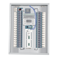
Example of a Tenant Improvement High Rise Core and Shell.
LCP 1
LCP 2
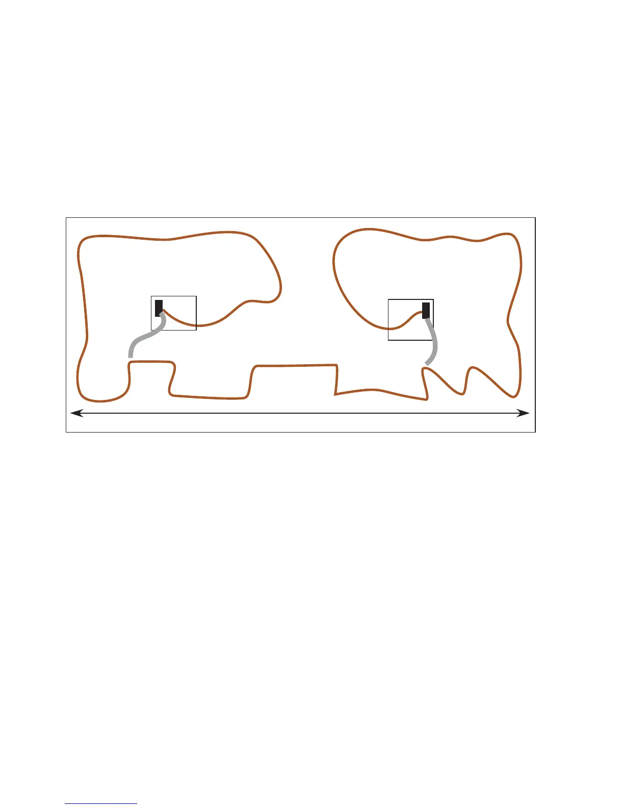
The booster wire can be 2 number 18s or just a short section
of Cat 5 with two pairs twisted together for +12 and two pairs
twisted together for Gnd.
Another solution is to get a “BUS BOOSTER” from LC & D
which is just a 12 volt power supply with RJ45 connectors on it
used to boost the voltage in the middle of the bus.
Also note: Never connect the bus “ground” to the actual “Earth”
ground. It is supposed to be a “floating” ground.
300 ft
$LV
$LV
$LV$LV
$LV
$LV
Add Gnd
&+12VONLY
Add Gnd
&+12VONLY
Getting out of trouble
Too Many Switches on a section of Bus
In this example the cat 5 Bus was wired before the equip-
ment and the manual were received. Though the electrician
knew what to do from a previous job he did not have this
number of switches on that job so had not run into this prob-
lem before.
By adding two sections of booster wire to boost the Ground
and +12 Volt connection he fixed his problem with voltage
drop to the switches.