Page 5
Power Amplier (& Powered Subwoofer) Connections
ANALOG AUDIO INPUTS
1
L R
2 3 4
L R
L R L R
7.1 CHANNEL OUTPUTS
L R
LS RS
LBS RBS C SUB
8
7
6 5 4 3
2
1
Inputs
Outputs
AB
ADA BUS
12VDC
AC 50/60Hz
90-260VAC~
ATTENTION!
MADE IN U.S.A.
OPTICAL DIGITAL
INPUTS
1
2
DIGITAL INPUTS
1
2
3
4
5
6
LAN 10/100
S
R
S
C
L
BS
R
BS
RS
R
LS
L
CL
LS
RS
L
BS
S
BR
Low Volatge Trigger
Pin 1 (-) to Gnd on 9-Pin D
Pin 2 (+) to Zn 1 on 9 Pin D
(Set PTM-8150 PAC Module
so all channels trigger with
Zone 1 and Normal Turn On)
Sub Output To
Power Amplifier
For Passive Subs
Or Sub Output To
Powered Subwoofer
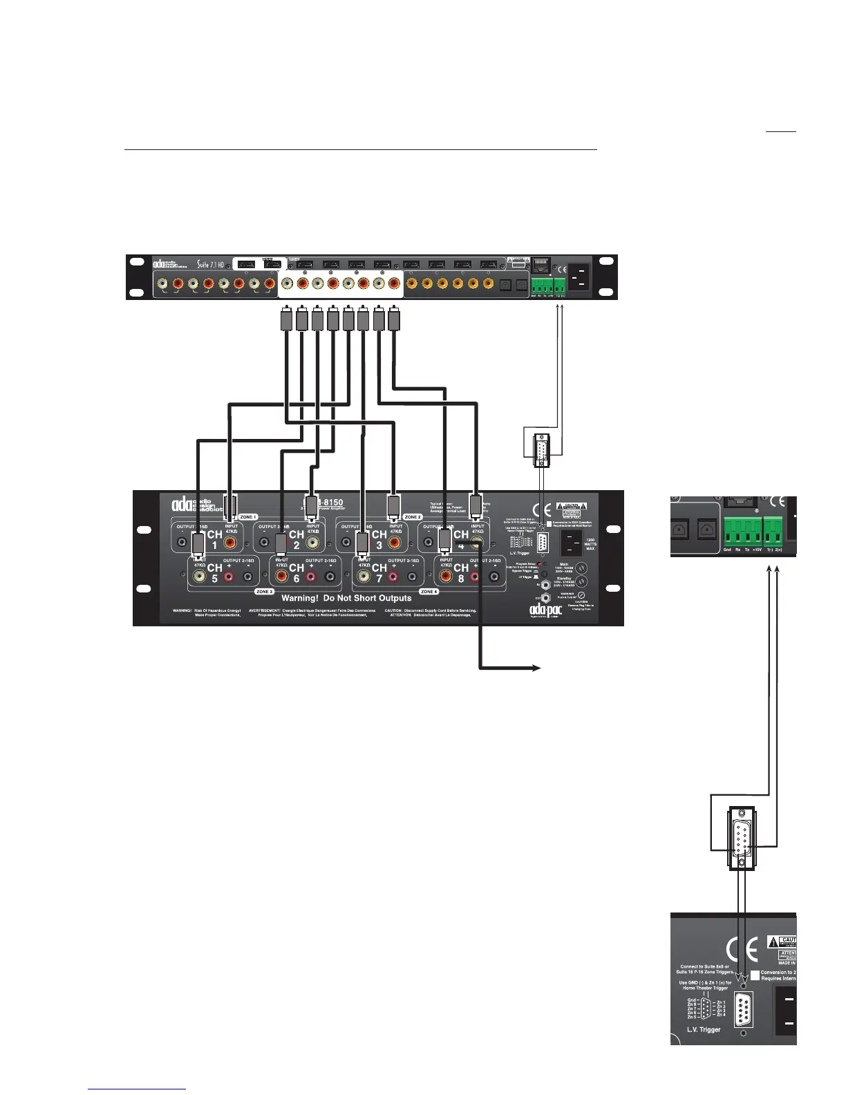
Audio Connections
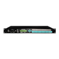
The Suite 7.1 HD’s Audio Outputs are clearly marked in a white eld on the back of the unit. ADA
strongly suggests not using directional interconnects that lift the grounds. This diagram includes ADA’s
PTM-8150 Eight Channel Power Amplier. While you may decide to vary the input arrangement if
you are using a PTM-8150, the following input arrangement will cause the amplier’s front panel LED
display to spread outward from Channel 4, the center channel speaker. If you are using a self-powered
subwoofer, you will connect the Suite 7.1 HD’s SUB Output directly to the subwoofer and you may opt
to “Y” split the SUB output to illuminate channel eight of the PTM-8150.
ANALOG AUDIO INPUTS
1
L R
2 3 4
L R
L R L R
7.1 CHANNEL OUTPUTS
L R
LS RS
LBS RBS C SUB
8
7
6 5 4 3
2
1
Inputs
Outputs
AB
ADA BUS
12VDC
AC 50/60Hz
90-260VAC~
ATTENTION!
MADE IN U.S.A.
OPTICAL DIGITAL
INPUTS
1
2
DIGITAL INPUTS
1
2
3
4
5
6
LAN 10/100
S
R
S
C
L
BS
R
BS
RSR LSL
CL
LS
RS
L
BS
S
BR
Low Volatge Trigger
Pin 1 (-) to Gnd on 9-Pin D
Pin 2 (+) to Zn 1 on 9 Pin D
(Set PTM-8150 PAC Module
so all channels trigger with
Zone 1 and Normal Turn On)
Sub Output To
Power Amplifier
For Passive Subs
Or Sub Output To
Powered Subwoofer
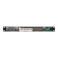
Low Voltage Power Amplier Trigger
The Suite 7.1 HD features two low voltage triggers that can be used among other
things, to turn ADA power ampliers on and off. Unlike the switched AC outlet,
which turns on and off with the Suite 7.1 HD, the low-voltage triggers are set to
track inputs on the preamplier. In the setup mode, you can determine if either
trigger one or trigger two (or both) engage with that input or not. When triggering
a power amplier using the low voltage triggers, ADA’s out of the box setup has
Trigger 1 engaging with all inputs.
ADA power with a PAC Module (Programmable Amplier Controller) permit ampli-
er channel pairs to be assigned to track independent zone triggers (for use in
multi-room systems). The ampliers can also be set to “Fast Turn On” so that the
amplier can be used for paging (amplier remains on and charged even when
the trigger is off). In a home theater system, zone triggering and fast turn on are
not required. If an ADA PAC amplier is ordered with an ADA home theater pre-
amplier, the unit will ship with all channel pairs set to trigger with Zn 1. Also, the
amplier will be set to “Normal Turn On” so that when the trigger is removed, the
amplier will turn off completely. Here, the Mach III will also ship with a 9-pin D
to two-wire cable that can be terminated to Low Voltage Trigger 1 on the Mach III
as shown in the adjacent diagram. Make certain that Low Voltage Trigger Button
on the back of the PAC amplier is in the outward “LV Trigger” position.
 Loading...