35
INSTALLATIONCONFIGURATIONOPERATION
FURTHER
INFORMATION
INDEX
APPENDIX 2 - LAYERS
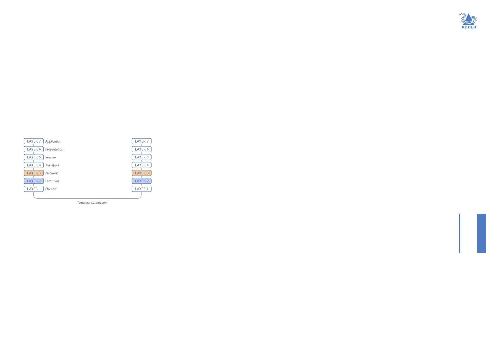
Layer 2 and Layer 3: The OSI model
When discussing network switches, the terms Layer 2
and Layer 3 are very often used. These refer to parts
of the Open System Interconnection (OSI) model, a
standardised way to categorize the necessary functions of
any standard network.
There are seven layers in the OSI model and these dene
the steps needed to get the data created by you (imagine
that you are Layer 8) reliably down onto the transmission
medium (the cable, optical bre, radio wave, etc.) that
carries the data to another user; to complete the picture,
consider the transmission medium is Layer 0. In general,
think of the functions carried out by the layers at the top
as being complex, becoming less complex as you go lower
down.
As your data travel down from you towards the
transmission medium (the cable), they are successively
encapsulated at each layer within a new wrapper (along
with a few instructions), ready for transport. Once
transmission has been made to the intended destination,
the reverse occurs: Each wrapper is stripped away and the
instructions examined until nally only the original data
are left.
So why are Layer 2 and Layer 3 of particular importance
when discussing AdderLink XDIP? Because the successful
transmission of data relies upon fast and reliable passage
through network switches – and most of these operate at
either Layer 2 or Layer 3.
The job of any network switch is to receive each
incoming network packet, strip away only the rst few
wrappers to discover the intended destination then
rewrap the packet and send it in the correct direction.
In simplied terms, the wrapper that is added at Layer
2 (by the sending system) includes the physical address
of the intended recipient system, i.e. the unique MAC
address (for example, 09:f8:33:d7:66:12) that is assigned
to every networking device at manufacture. Deciphering
recipients at this level is more straightforward than at
Layer 3, where the address of the recipient is represented
by a logical IP address (e.g. 192.168.0.10) and requires
greater knowledge of the surrounding network structure.
Due to their more complex circuitry, Layer 3 switches are
more expensive than Layer 2 switches of a similar build
quality and are used more sparingly within installations.