INSTALLATION
3
CONFIGURATIONOPERATION
FURTHER
INFORMATION
INDEX
ADDERLINK XDIP FEATURES
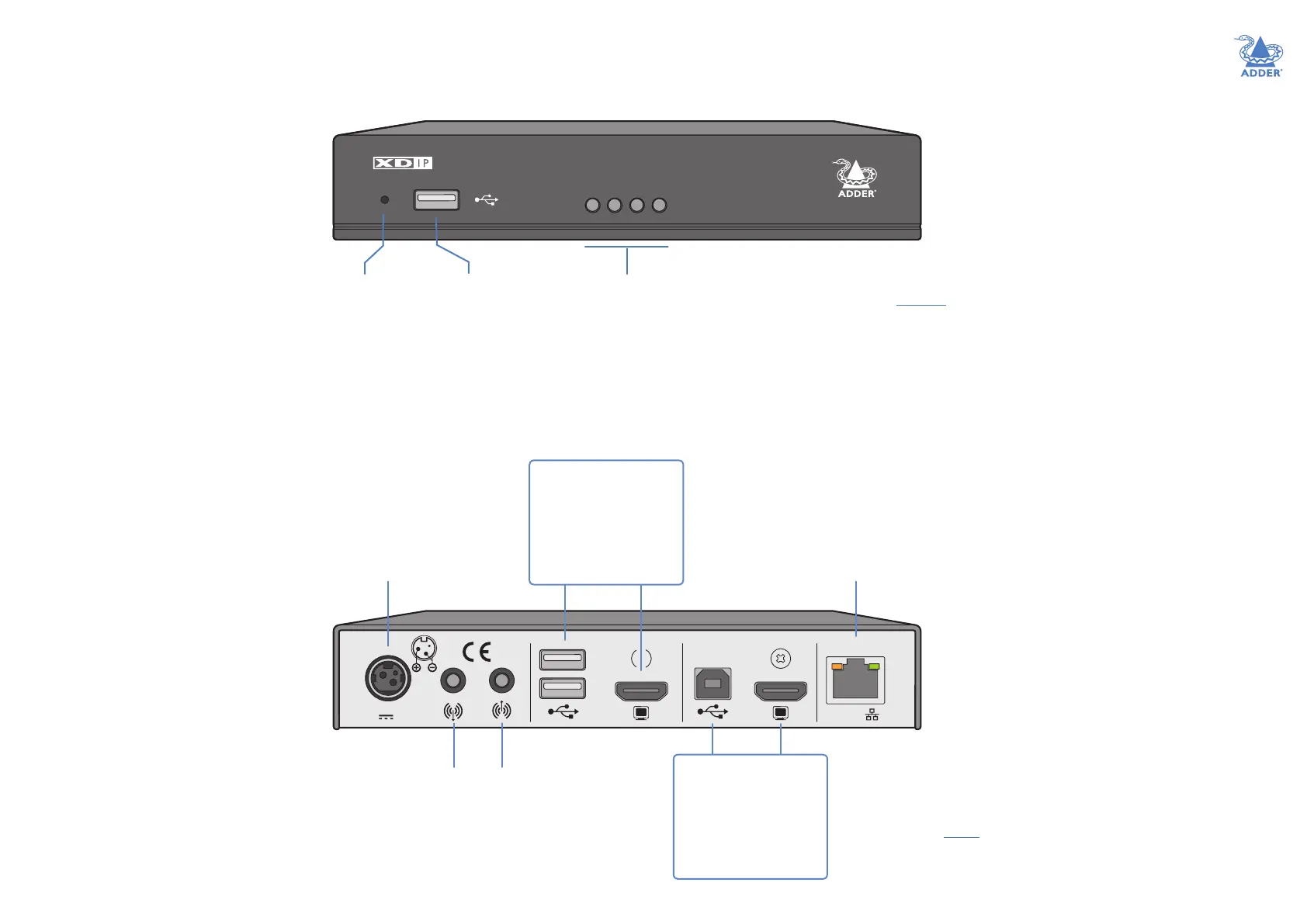
AdderLink XDIP nodes are contained within slimline metal casings measuring just 169 x 112 x 31mm.
www.adder.com
ADDERLINK
LNKUSB VID PWR
USB port
Available for
console use on
receiver and
transmitter nodes.
Recessed
reset
button
See
“Restoring
a node” on
page 19.
Status indicators
These provide visual conrmation of various system functions. See Indicators for
further details.
LNK - indicates the presence of a valid data link.
USB and VID - indicate active USB and video connections.
PWR - indicates the presence of input power (the color also indicates overall mode:
TX: Green, RX: Blue, Start of Life: Red, Recovery mode: Yellow).
12V 1.5A
INDOOR USEONLYCOMPUTERCONSOLE
PoE
Audio
line
out
jack
Audio
line
in
jack
HDMI
video port
12VDC power
port
(PoE option
available)
USB
ports
On TX: [Optional] Feed
to a local console
On RX: Feed to the
user console
HDMI
video port
USB
port
On TX: Link to the
main computer
On RX: [Optional] Link
to a local computer
Data link - either
connect directly to
another node or
indirectly to multiple
others via a supported
network switch*
(PoE 802.3af supported)
* The network switch used must:
• Support 1Gb transfer rates.
• Support IGMP (Internet Group Management
Protocol) to at least level 2 (preferably level 3).
• Have IGMP Fast Leave and IGMP Snooping enabled.