7
INSTALLATIONCONFIGURATIONOPERATION
FURTHER
INFORMATION
INDEX
Computer connections
Computer connections are always made at the transmitter node, but can also optionally
be made at the receiver node, where channel switching between local and remote
computer sources is required.
Notes:
• When a local computer is connected to a receiver node, it can only be accessed from that
receiver, no other receivers can gain access to it.
• Video resolutions up to 1920 x 1200 @ 60Hz are supported.
• HDMI audio is not supported; please use the audio in/out ports to transfer audio signals.
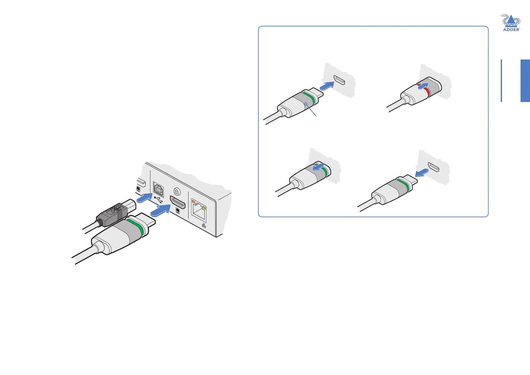
To make computer connections
1 Insert the supplied HDMI cable between the HDMI video socket (in the COMPUTER
section) and the video output port on the computer.
HDMI offers the great advantage that it is a straightforward task to convert its signals
to and from other common video formats (DisplayPort, DVI and VGA) - See page 8.
2 Insert the supplied USB type A to type B cable between the USB socket (in the
COMPUTER section) and a vacant USB port on the computer.
Using Adder locking HDMI connectors
The supplied HDMI cable features a locking mechanism to prevent accidental
disconnections. Please follow the procedures below when inserting and removing them:
Insertion
2 Push the locking
collar forward
(to show red).
1 With the locking collar
pulled back (to show
green), insert the
connector.
Locking collar
Removal
1 Pull the locking
collar back (to
show green).
2 Gently pull
the connector
to disengage
it from the
socket.
IMPORTANT: Do not attempt to insert or remove
the connector while the red band is shown.
INDOOR USE ONLYCOMPUTERE
PoE
USB connection
to computer
HDMI video
connection to
computer