MNALAZIN-02 8
Products and System Requirements / Feedback Supported
Feedback Supported
ThereareanumberofdifferentfeedbackoptionsavailableintheAZfamilyofanalogdrives.
Thefeedbackelementcanbeanydevicecapableofgeneratingavoltagesignalproportionalto
current,velocity,position,oranyparameterofinterest.Suchsignalscanbeprovideddirectly
byapotentiometerorindirectlybyotherfeedbackdevicessuchasHallSensorsorEncoders.
TheselatterdevicesmusthavetheirsignalsconvertedtoaDCvoltage,ataskperformedbythe
AZdrivecircuitry.
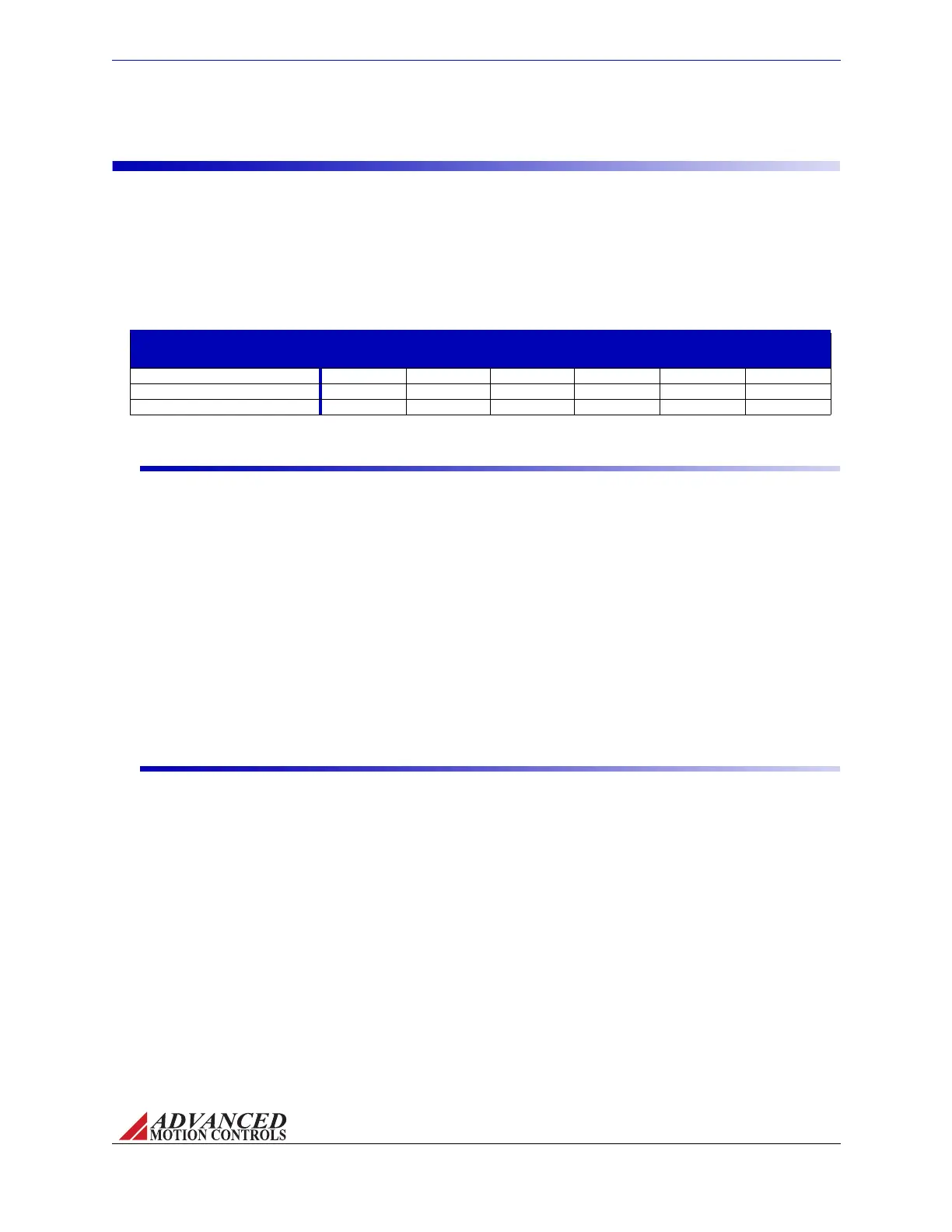
TABLE 2.3 Feedback Supported
Feedback Supported
Description AZ AZB AZ_DDC AZBDC AZBE AZBH
Hall Sensors for Commutation D D D D
Hall Sensors for Velocity Control D
Single- Ended Incremental Encoder D
Feedback Polarity
Thefeedbackelementmustbeconnectedfornegativefeedback.Thiswillcauseadifference
betweenthecommandsignalandthefeedbacksignal,calledtheerrorsignal.Thedrive
comparesthefeedbacksignaltothecommandsignaltoproducetherequiredoutputtothe
loadbycontinuallyreducingtheerrorsignaltozero.ForAZdrives,thisbecomesimportant
whenusing“EncoderFeedback”and“HallSensors”,asconnectingthesefeedbackelements
forpositivefeedbackwillleadtoamotor"run‐away"condition.Inacasewherethefeedback
linesareconnectedtothedrivewiththewrongpolarityineitherHallVelocityorEncoder
VelocityMode,thedrivewillattempttocorrectthe"errorsignal"byapplyingmorecommand
tothemotor.Withthewrongfeedbackpolarity,thiswillresultinapositivefeedbackrun‐away
condition.Tocorrectthis,eitherchangetheorderthatthefeedbacklinesareconnectedtothe
drive,orchangeSwitch4ontheDIPswitchbanktotheoppositesettingtoreversetheinternal
feedbackvelocitypolarity.SeethedrivedatasheetformoreinformationonDIPswitchsettings.
Hall Sensors
DCThreePhase(Brushless)AZdrivesusesingle‐endedHallSensorsforcommutation
feedback,andinthespecialcaseoftheAZBHxxA8drives,forvelocitycontrol.TheHallSensors
(typicallythree)arebuiltintothemotortodetectthepositionoftherotormagneticfield.These
sensorsaremountedsuchthattheyeachgenerateasquarewavewith120‐degreephase
differenceoveroneelectricalcycleofthemotor.Dependingonthemotorpolecount,there
maybemorethanoneelectricalcycleforeverymotorrevolution.Foreveryactualmechanical
motorrevolution,thenumberofelectricalcycleswillbethenumberofmotorpolesdividedby
2.Forexample:
• a6‐polemotorcontains3electricalcyclespermotorrevolution
• a4‐polemotorcontains2electricalcyclespermotorrevolution
• a2‐polemotorcontains1electricalcyclepermotorrevolution.
ThedrivepowerstwoofthethreemotorphaseswithDCcurrentd
uringeachspecificHall
Sensorstate:
Artisan Technology Group - Quality Instrumentation ... Guaranteed | (888) 88-SOURCE | www.artisantg.com