MNALAZIN-02 27
Integration in the Servo System / Interface Circuitry Examples
• KeephighcurrenttracesshortTracescarryinghighcurrent,suchastheDCPower
tracesandMotorSignaltraces,shouldbekeptshortandclosetogethertominimizenoise
emissions.Also,keepDCPowertracesseparatefromMotorSignaltraceswherepossible.
• Designformaximumval uesAdjacenttracescancarryavoltagepotentialequaltothe
maximumDCpowersupplyvalue,andcarrycurrentofboththeAZservodrive’speakand
continuouscurrentratings.Thetracewidthandcopperplatingthicknesswillneedtotake
thesemaximumvaluesintoaccount.Also,beawarethatAZservodrivepinheadershavea
maximumcurrentratingof3ampsDCperpin.Inordertoachieveahigheroverallpeak
currentcapability,somehighcurrentsignals"share"agroupofpinstospreadthecurrent
betweenthem.Highcurrenttracesrunningtothesepingroupsshouldbeinter‐connected
onthePCBboard.Consultthedrive’sdatasheetorthe"Pinouts"sectionin“Products
Covered”onpage5forthesepingroupings.
Interface Circuitry Examples
Thefollowingsectionsshowexamplesofhowaninterfaceboardcouldbedesignedtowork
withanAZservodrive,andalsocontaingeneralconnectionrulesandinstructions.
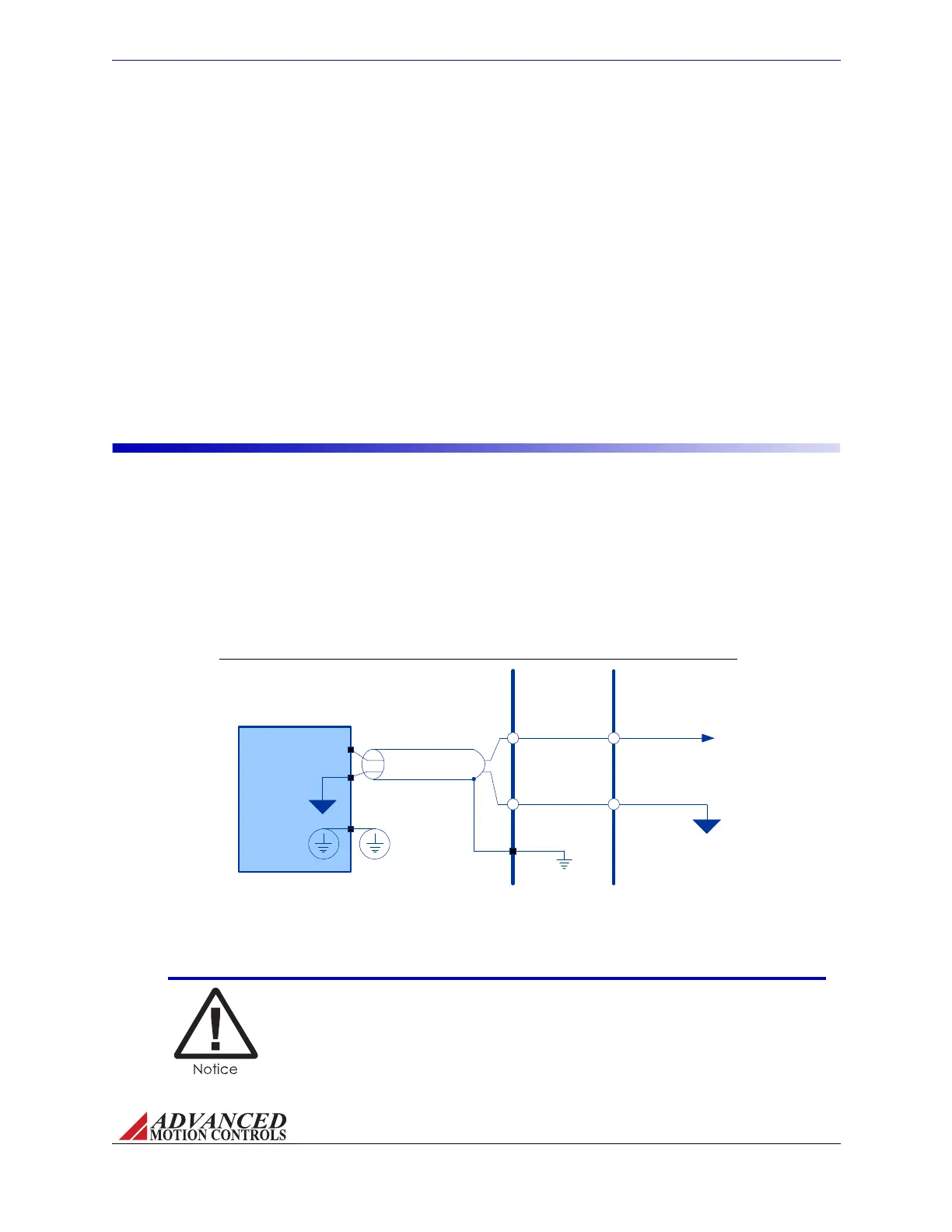
FIGURE 3.7 DC Power Input Wiring
INTERFACE
PCB
AZ SERVO
DRIVE
High Voltage
Isolated DC
Power
Supply
Shield
Single Point
System Ground
(PE Ground)
Power Ground
+HV
GND
Chassis Ground
DC Power Input ThediagrambelowshowshowanAZservodriveconnectstoanisolatedDC
PowerSupplythroughamountingcard/interfacePCB.Noticethatthepowersupplywiresare
shielded,andthatthepowersupplycaseisgroundedatthesinglepointsystemground(PE
Ground).ThecableshieldshouldbegroundedatthemountingcardorPCBinterfacesideto
chassisground.
Depending on the power capacity of the AZ drive model being used
there may be multiple pins for DC Input Power connections. Refer to the
datasheet of the specific model being used. The maximum current
capacity per pin is 3A continuous.
Artisan Technology Group - Quality Instrumentation ... Guaranteed | (888) 88-SOURCE | www.artisantg.com