FIGURE 3.10
INTERFACE
PCB
AZ SERVO
DRIVE
+5V
Hall 1 (P1-8)
Hall A
+5V
Hall 2 (P1-9)
+5V
Hall 3 (P1-10)
Hall B
Hall C
5k
5k
5k
Motor
Shield
+V Hall Out (P1-6)
Signal Ground (P1-7)
Hall
Power
Hall
Ground
Chassis Ground
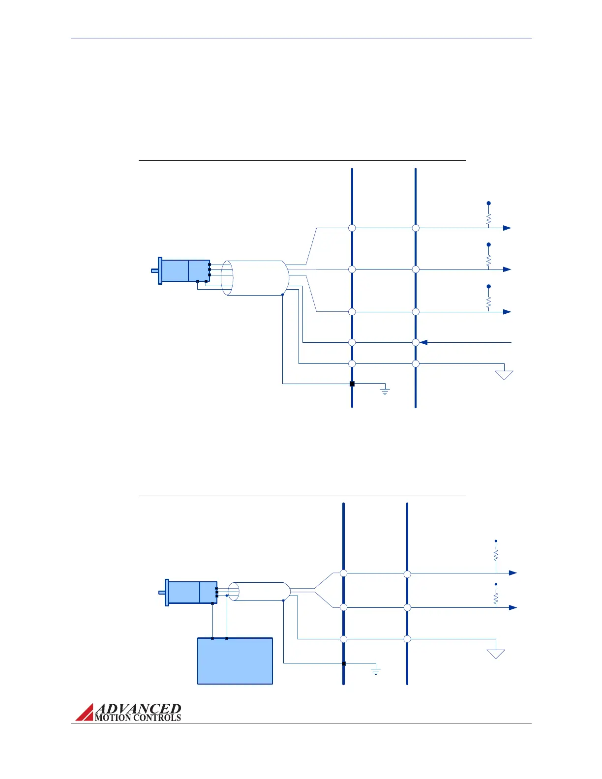
Hall Sensor Interface Wiring
FIGURE 3.11
INTERFACE
PCB
AZ SERVO
DRIVE
Encoder A In (P1-14)
Encoder B In (P1-13)
Encoder-A
Encoder-B
Motor
Shield
+5V
+5V
10k
10k
+VDC Power
Supply for
Encoder
+V
GND
Signal Ground (P1-2)
Chassis Ground
Encoder Input Interface Wiring
MNALAZIN-02 29
Integration in the Servo System / Interface Circuitry Examples
Hall Sensor Inputs BrushlessAZdrivesallowsingle‐endedHallSensorinputsbothfor
commutation,andinthespecialcaseofAZBHxxA8drives,forvelocityfeedback.AZdrives
providea+6VlowpowersupplytopowertheHallSensors.Belowistherecommended
circuitrywhendesigningamountingcardtointerfacewithanAZdrive.
Encoder Inputs AZBExxA8drivessupportsingle‐endedincrementalencoderinputs.The
encodermustbepoweredbyanexternalpowersupply.Checkthemotorandencoder
specificationsfortheencodervoltageandcurrentrequirements.Belowistherecommended
circuitrywhendesigningamountingcardtointerfacewithanAZdrive.
Artisan Technology Group - Quality Instrumentation ... Guaranteed | (888) 88-SOURCE | www.artisantg.com