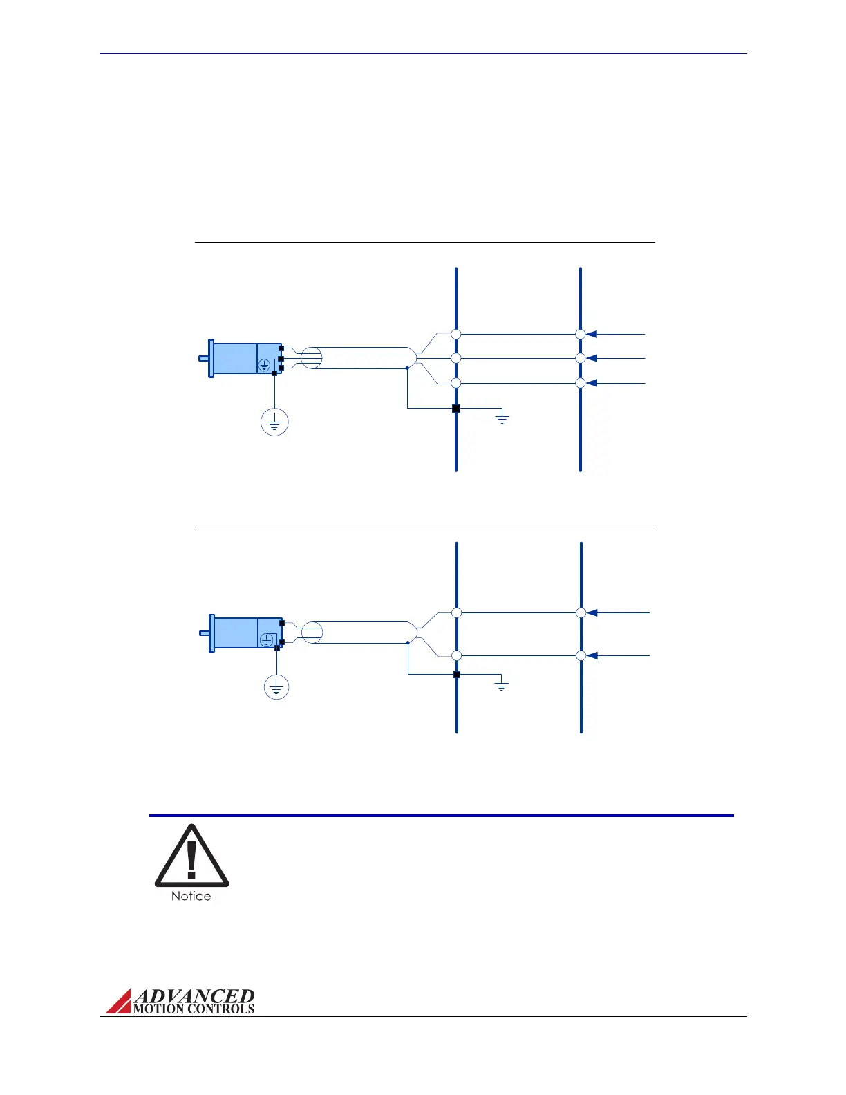
FIGURE 3.9 Single Phase Motor Power Output Wiring
INTERFACE PCB
AZ SERVO
DRIVE
Shield
Motor A
Motor B
Motor
Single Point
System Ground
(PE Ground)
Chassis Ground
FIGURE 3.8 Three Phase Motor Power Output Wiring
INTERFACE PCB
AZ SERVO
DRIVE
Shield
Motor C
Motor B
Motor A
Motor
Single Point
System Ground
(PE Ground)
Chassis Ground
MNALAZIN-02 28
Integration in the Servo System / Interface Circuitry Examples
Motor Power Output ThediagrambelowshowshowanAZservodriveconnectstoamotor
throughamountingcard/interfacePCB.Bothbrush‐typeandbrushlessmotorsshouldfollow
thisgeneralsetup.Noticethatthemotorwiresareshielded,andthatthemotorhousingis
groundedtothesinglepointsystemground(PEGround).Thecableshieldshouldbegrounded
atthemountingcardorPCBinterfacesidetochassisground.
Depending on the power capacity of the AZ drive model being used
there may be multiple pins for Motor Power connections. Refer to the
datasheet of the specific model being used. The maximum current
capacity per pin is 3A continuous.
Artisan Technology Group - Quality Instrumentation ... Guaranteed | (888) 88-SOURCE | www.artisantg.com