MNALAZIN-02 25
Integration in the Servo System / Mounting
Soldering SolderinganAZboarddirectlytoaPCBprovidesaddedsupportagainstmechanical
shocksandvibration.ItisrecommendedtosolderAZdrivestoaPCBfollowingtheindustry
standardforAcceptabilityofElectronicAssembliesIPC‐A‐610D.Usesolderwithno‐cleanflux.
AZdrivescanbesolderedbyanyofthefollowingmethods:
• wavesoldering
• handsoldering
• selectivewavesoldering
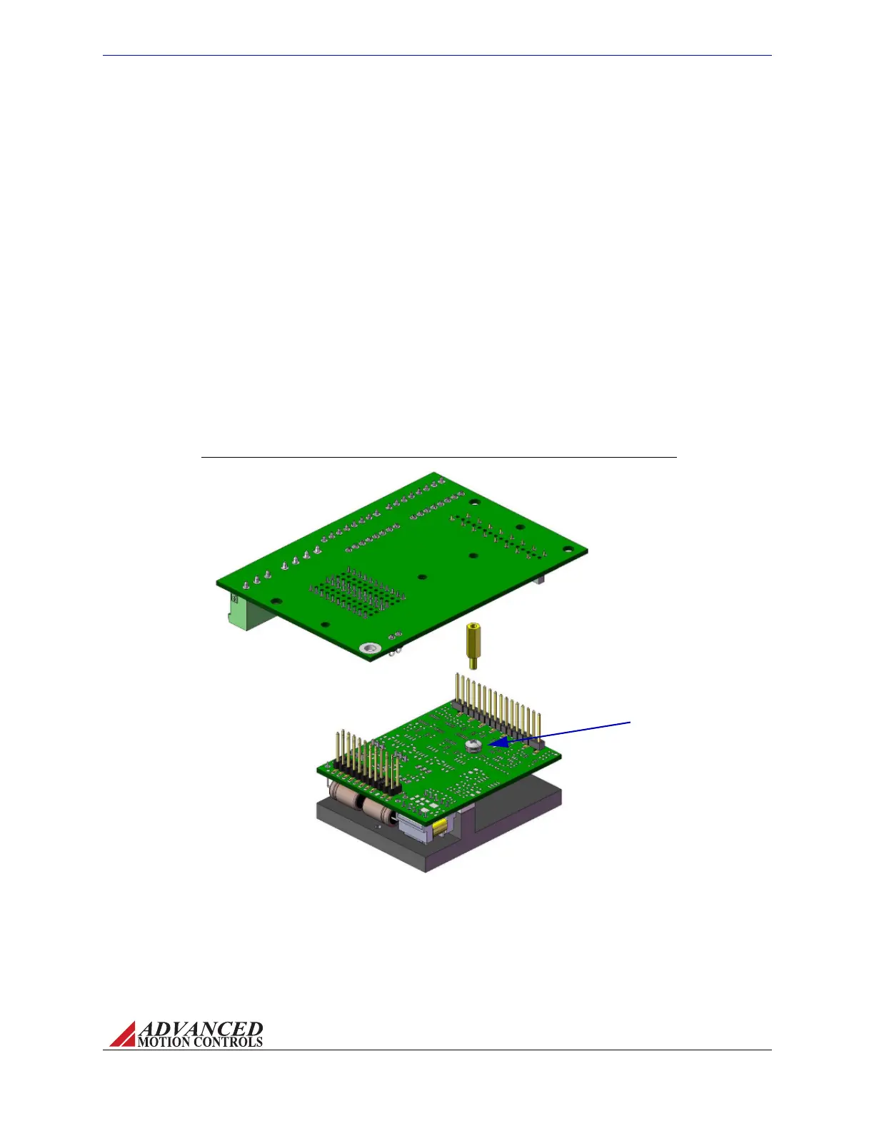
FIGURE 3.5
Remove drive mounting screw,
and replace with spacer*. Use
the removed drive mounting
screw to secure mounting card
to drive from the bottom of the
mounting card through the
spacer after drive has been
inserted in mounting card
socket connectors.
*Spacer not included with AZ drive or
mounting card. Spacer shown is
standard 3/16" hex 4/40 thread,
male/female, 7/16" length.
Drive Mounting Screw
AZ20 Screw Mount Diagram
TocleanthePCBanddriveaftersoldering,itisrecommendedtogentlyapplyisopropylalcohol
oracleaningagentwithasoft‐bristledbrush.Usecarenottoapplydownwardpressure,but
ratherlightlybrushthePCBanddrive.Donotimmersethedriveinacleaningagent.
Screw Mounting Foraddedstabilityandsupport,AZdrivescanbemountedwithscrewsin
tandemwithoneoftheoptionsabove.Figure3.5showshowanAZ20drivecanbemountedto
theMC1XAZ01mountingcardusingaspacer.See“PhysicalDimensions”onpage39and/or
thespecificdrive’sdatasheetforexactscrewlocationsanddimensions.
Artisan Technology Group - Quality Instrumentation ... Guaranteed | (888) 88-SOURCE | www.artisantg.com