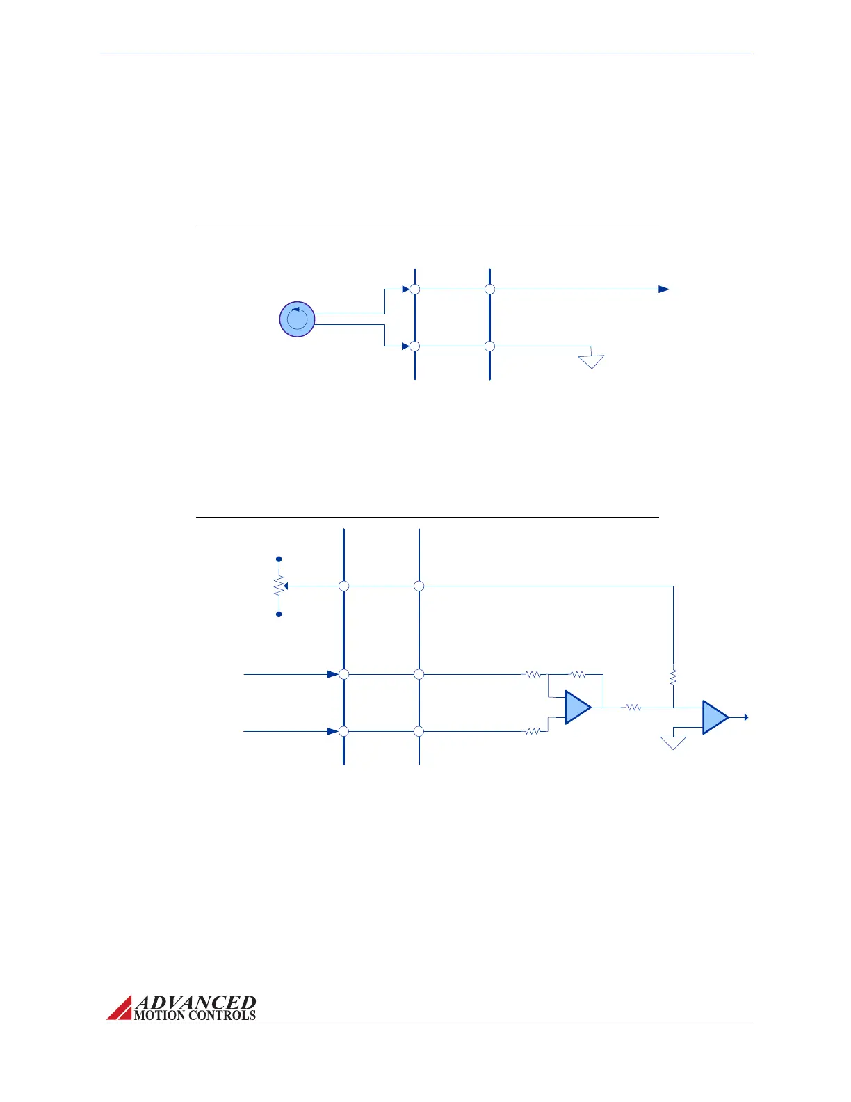
FIGURE 3.12 DC Tachometer Input Wiring
AZ SERVO
DRIVE
VEL MONITOR OUT / TACH IN
SIGNAL GROUND
Tachometer
(+/- 60 VDC)
INTERFACE
PCB
Tach+
Tach-
FIGURE 3.13 Offset Input Wiring
AZ SERVO
DRIVE
+10V Max
OFFSET (P1-16)
Offset
Potentiometer
-10V Max
-
+
-
+
5k
500k
40k
40k
+REF IN (P1-1)
-REF IN (P1-3)
15k
Input
Command
Signal
INTERFACE
PCB
MNALAZIN-02 30
Integration in the Servo System / Interface Circuitry Examples
Tachometer Input FordrivemodelsthatallowanexternalDCTachometerforvelocitycontrol,
thetachometerisconnectedbetweentheVelocityMonitorOutput/TachometerInputpin(P1‐
15)andsignalground(eitherP1‐7orP1‐2).Thetachometerislimitedtoafeedbackvoltage
rangeof±60VDC.Thediagrambelowshowstherecommendedconnectionmethod.
Offset Input Fordrivemodelsthathaveanexternaloffsetinputoption,apotentiometercanbe
usedinadditiontotheinputcommandsignalwhenaninputoffsetadjustmentisdesired.The
diagrambelowshowsonepossibleconnectionmethodusingapotentiometerfortheoffset
input.
Artisan Technology Group - Quality Instrumentation ... Guaranteed | (888) 88-SOURCE | www.artisantg.com