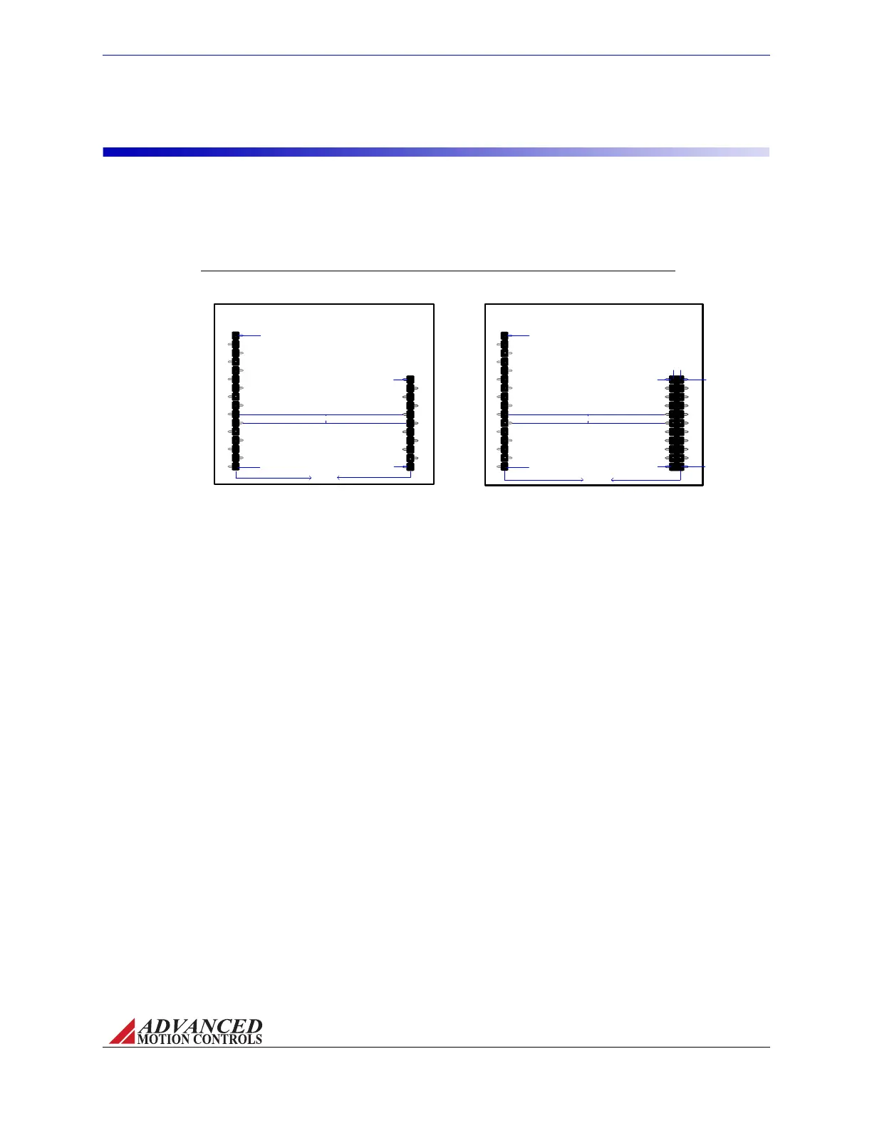
FIGURE 2.4 AZ-series Pin Layouts
PIN 1b
PIN 1a
PIN 11a
PIN 11b
PIN 1
PIN 16
P1 - Signal
Connector
P2 - Power
Connector
0.10in [2.54mm]
[55.88mm]
2.20in
0.10in [2.54mm]
PIN 1
PIN 11
PIN 16
P1 - Signal
Connector
P2 - Power
Connector
PIN 1
[2.54mm]
[55.88mm]
2.20in
0.10in
AZ6andAZ12Drives
AZ20Drives
MNALAZIN-02 11
Products and System Requirements / Pin Layout
Pin Layout
ThediagramsbelowshowthepinlayoutandlocationonAZdrives,asseenfromthePCB
wherethedriveismounted.NotethatAZ20drivesusesadoublerowforthepowerheader.
Moredetaileddimensionalinformationcanbefoundin“PhysicalDimensions”onpage39and
in“MatingConnectors”onpage24.
Artisan Technology Group - Quality Instrumentation ... Guaranteed | (888) 88-SOURCE | www.artisantg.com