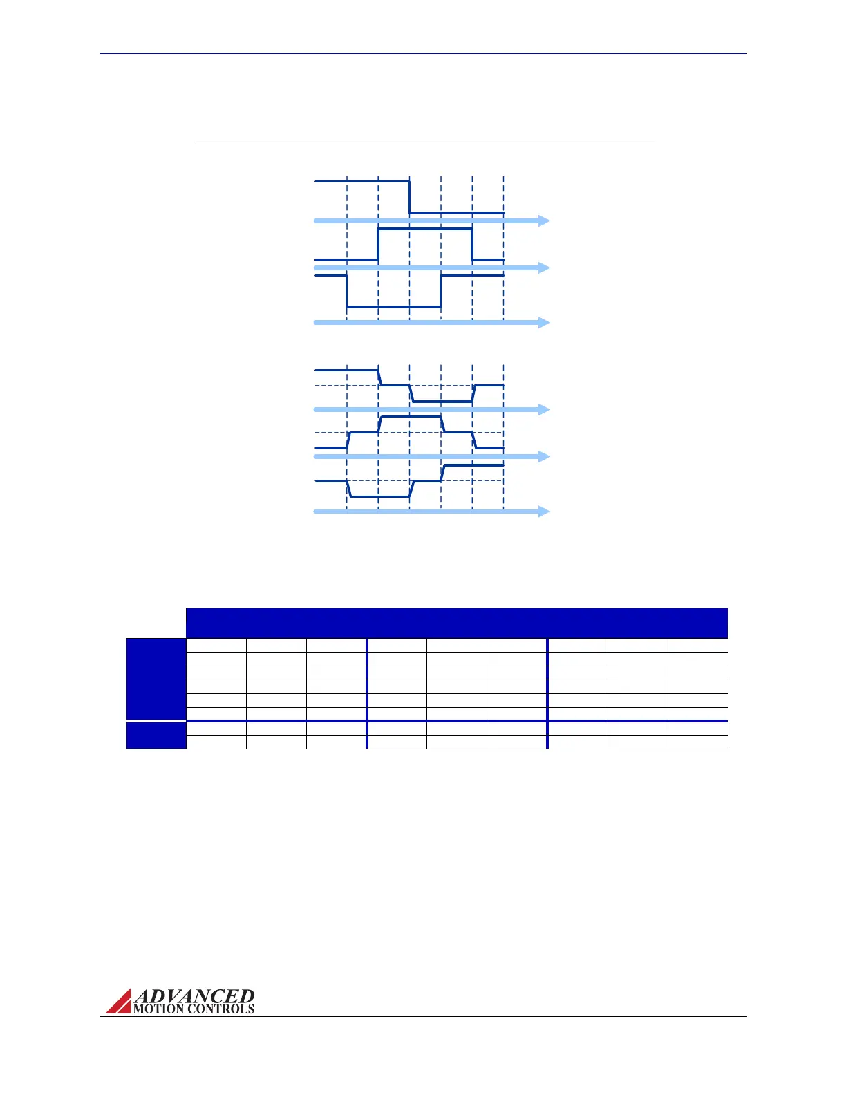
FIGURE 2.2 Hall Sensor Commutation and Motor Phase Current for 120-Degree Phasing
Electrical Degrees
Motor Phase
Current
0
60 120 180
240 300 360
Hall A
Hall B
Hall C
High (1)
Low (0)
High (1)
Low (0)
High (1)
Low (0)
Phase A
Phase B
Phase C
Hall Sensor
Commutation
Electrical Degrees
0
60 120 180
240 300 360
High
Low
High
Low
High
Low
MNALAZIN-02 9
Products and System Requirements / Feedback Supported
Thetablebelowshowsthevalidcommutationstatesforboth120‐degreeand60‐degree
phasing.
TABLE 2.4 Commutation Sequence T
able
60 Degree 120 Degree Motor
Hall 1 Hall 2 Hall 3 Hall 1 Hall 2 Hall 3 Phase A Phase B Phase C
Valid
1 0 0 1 0 0 HIGH - LOW
1 1 0 1 1 0 - HIGH LOW
1 1 1 0 1 0 LOW HIGH -
0 1 1 0 1 1 LOW - HIGH
0 0 1 0 0 1 - LOW HIGH
0 0 0 1 0 1 HIGH LOW -
Invalid
1 0 1 1 1 1 - - -
0 1 0 0 0 0 - - -
Bydefault,AZdrivesarealwayssetto120‐degreephasing.Threephase(Brushless)drivesdo
howeverhaveasurface‐mountjumper(JE2)onthedrivePCBthatcanberemovedto
manuallysetthedriveto60‐degreephasing.
Using a Single Phase Motor with a Three Phase Drive ThreePhase(Brushless)
drivesarealsocompatiblewithSinglePhase(Brushed)motors.However,becausethereareno
HallSensorsonabrushedmotor,oneofthefollowingcourseofactionsmustbetakento
properlycommutatethedrive:
• RemovetheJE2jumpertosetthedrivefor60‐degreephasing.LeavealltheHallSensor
inputsonthedriveopen.Theseinputsareinternallypulledhighto+5V,creatinga"1‐1‐1"
Artisan Technology Group - Quality Instrumentation ... Guaranteed | (888) 88-SOURCE | www.artisantg.com