MNALAZIN-02 18
3 Integration in the Servo System
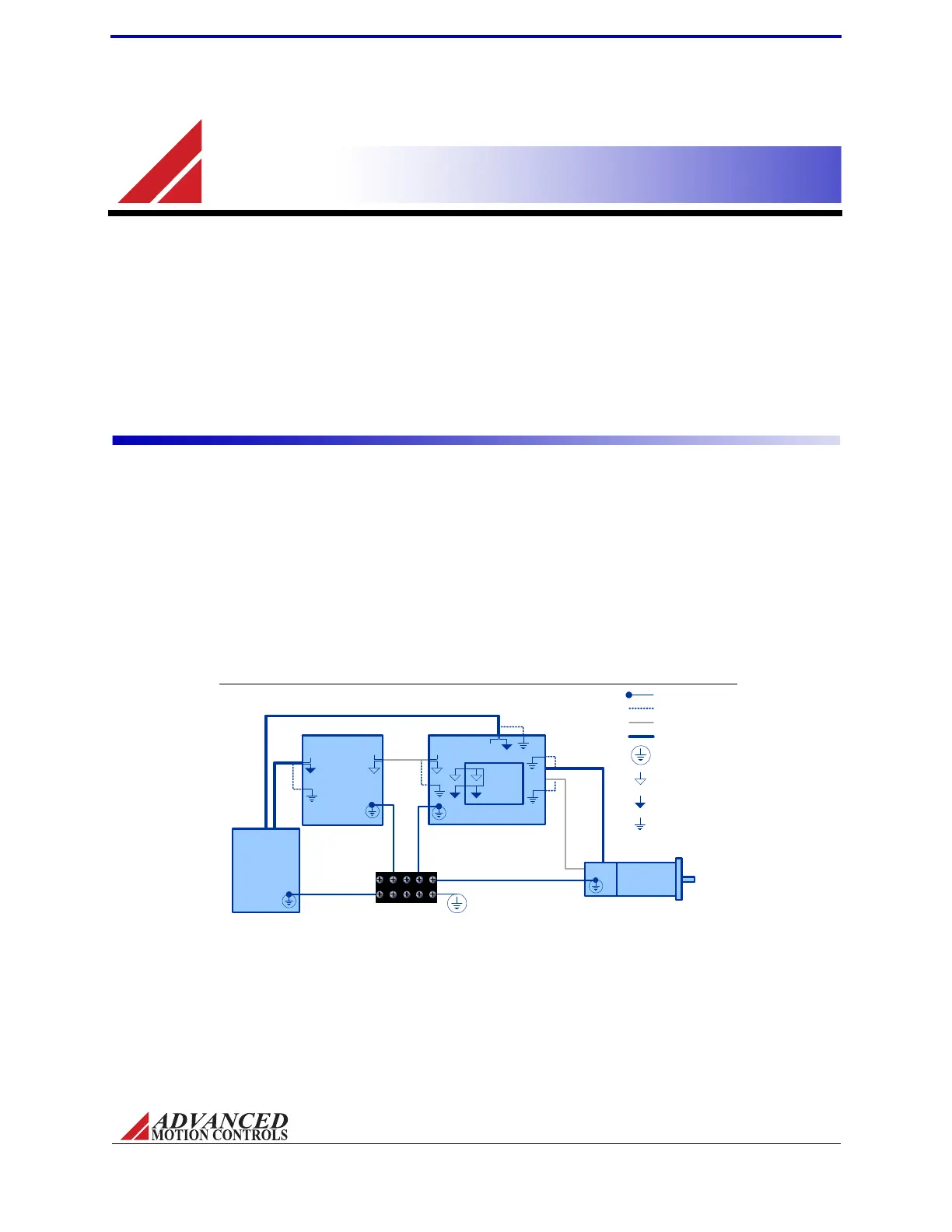
FIGURE 3.1
Shield Ground Wire
Case Ground Wire
Shielded Feedback/Signal Cable
Shielded Power Cable
Motor
Single Point System
Ground (PE Ground)
AZ Drive
PCB Interface
Controller
Isolated DC
Power Supply
+VDC
+VDC
PE Ground
Signal Ground
Power Ground
Command
Signal
Command
Signal
Chassis Earth Ground
System Grounding
ThischapterwillgivevariousdetailsonincorporatinganAZservodriveintoasystem,suchashowtodesignthe
PCBtracesonaninterfaceboard,howtoproperlygroundboththeAZdrivealongwiththeentiresystem,and
howtoproperlyconnectmotorwires,powersupplywires,feedbackwires,andinputsintotheAZdrive.
Grounding
InmostservosystemsallthecasegroundsshouldbeconnectedtoasingleProtectiveEarth
(PE)groundpointina"star"configuration.GroundingthecasegroundsatacentralPEground
pointreducesthechanceforgroundloopsandhelpstominimizehighfrequencyvoltage
differentialsbetweencomponents.Allgroundwiresmustbeofaheavygaugeandbeasshort
aspossible.ThefollowingshouldbesecurelygroundedatthecentralPEgroundingpoint:
• Motorchassis
• Controllerchassis
• Powersupplychassis
• PCBInterfacechassis
GroundcableshieldwiresatthemountingcardorPCBinterfacesidetoachassisearthground
point.
Artisan Technology Group - Quality Instrumentation ... Guaranteed | (888) 88-SOURCE | www.artisantg.com