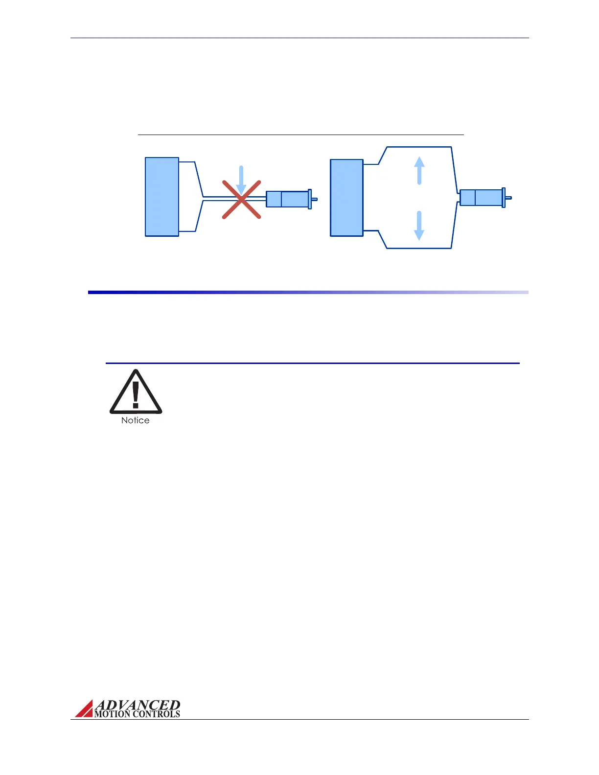
FIGURE 3.2 Feedback Wiring
Motor Feedback
Motor Power
Avoid running
feedback and power
wires together
Motor Feedback
Motor Power
Separate power and
feedback wires
where possible
Motor
AZ SERVO
DRIVE
Motor
AZ SERVO
DRIVE
MNALAZIN-02 21
Integration in the Servo System / Wiring
motor,trytofindseparatepathsthatmaintaindistancebetweenthetwo.Aruleofthumbfor
theminimumdistancebetweenthesewiresis10cmforevery10mofcablelength.
Input Reference Wires
Useofatwisted,shieldedpairfortheinputreferencewiresisrecommended.Connectthe
referencesource"+"to"+REFIN",andthereferencesource"‐"(orcommon)to"‐REFIN".
ConnecttheshieldtothemountingcardorPCBinterfacechassisground.Theservodrive’s
referenceinputcircuitwillattenuatethecommonmodevoltagebetweensignalsourceand
drivepowergrounds.
In case of a single-ended reference signal, connect
the command
signal to "+ REF IN" and connect the command return and "- REF IN" to
signal ground.
Longsignalwires(10‐15feetandup)canalsobeasourceofno
isewhendrivenfromatypical
OP‐AMPoutput.DuetotheinductanceandcapacitanceofthewiretheOP‐AMPcanoscillate.It
isalwaysrecommendedtosetafixedvoltageatthecontrollerandthencheckthesignalatthe
drivewithanoscilloscopetomakesurethatthesignalisnoisefree.
Artisan Technology Group - Quality Instrumentation ... Guaranteed | (888) 88-SOURCE | www.artisantg.com