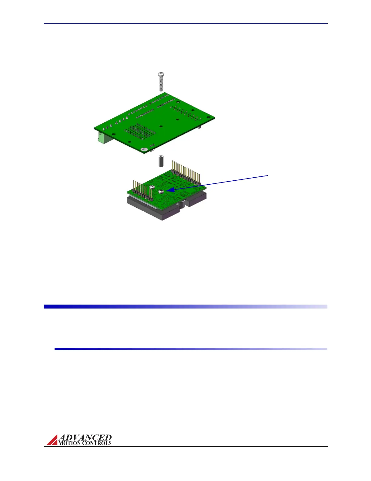
FIGURE 3.6 AZ6/AZ12 Screw Mount Diagram
Remove drive mounting screw,
and align spacer* over empty
screw hole on drive PCB. Use a
4/40 thread, 1" screw to secure
mounting card to drive from the
bottom of the mounting card
through the spacer after drive
has been inserted in mounting
card socket connectors.
*Spacer not included with AZ drive or
mounting card. Spacer shown is #4
clear, 7/16" length.
Drive Mounting Screw
MNALAZIN-02 26
Integration in the Servo System / PCB Design
AZdrivescanalsobescrewmountedthroughtwo4/40threadscrewholesoneithersideof
theAZbaseplateontoanexternalheatsinkorothermountingplateforaddedstabilityand
resiliencyagainstmechanicalvibration.Mountingtoanexternalheatsinkalsoprovidesbetter
thermalmanagementbehaviorthanothermountingoptions.See“AmbientTemperature
RangeandThermalData”onpage17formoreinfo.
PCB Design
WhendesigningaPCBboardtointerfacewithanAZdrive,therearesomekeyfeaturesthat
mustbekeptinmindtoensureproperoperation.
Trace Width and Routing
TheproperdesignandimplementationofthePCBtracesonaninterfacecardisessentialin
maximizingdriveefficiencyandnoisereduction.
• Keephighandlo w powersignalsseparatedAlthoughAZservodriveshaveaninternal
connectionbetweenpowerandsignalground,thetracesemittingfromthePower
Connector,P2,carryhighcurrentsandvoltages,whilethetracesemittingfromtheSignal
Connector,P1,carrylowcurrentsvoltages.RefrainfromroutingtracesfromP2neartraces
fromP1,andneverroutetheminparallel.Ifpowertracesandsignaltracesneedtocross,
theyshoulddosoatrightangles.
Artisan Technology Group - Quality Instrumentation ... Guaranteed | (888) 88-SOURCE | www.artisantg.com