MNALAZIN-02 34
Operation / Getting Started
Connections Test Beforeapplyingpowertothedrive,connecttheAZdrivetothemounting
cardorPCBinterface,usinganyofthemountingoptionsfrom“Mounting”onpage23.Using
anohmmeterordigitalmultimeter,testtheconnectionsbetweenthemountingcardorPCB
interfaceheadersandtheAZdrivepins.Checkforanyshortsoropencircuits.Atthispoint,
alsocheckthegroundconnectionofthewholesystem(AZdrive,mountingcard,Motor).All
theseelementsshouldhavetheircaseorchassisconnectedtoacentralgroundingpointina
"star"configuration.Forreview,see“Grounding”onpage18.
Power Supply
1. BeforewiringtheDCpowersupplytothemountingcardandAZdrive,useavoltmeteror
digitalmultimetertomakesuretheDCvoltageleveliswithinspecifications.
2. Do
notturnontheDCpowersupplyyet.ConnecttheDCpowersupplywirestothe
mountingcardorPCBinterface.DonotconnectdirectlytotheAZdriveheaderpins.Be
surethehighvoltageandgroundconnectionsdonotgetreversed,asthiswilldamagethe
drive.
3. T
urnontheDCpowersupply.MonitortheDCvoltageonthemountingcardtestpointsor
PCBinterfacetobesurethevoltageleveliswithinspecifications.Oncecertainthatpower
isbeingproperlyappliedtotheAZdrive,turntheDCpowersupplyoff.
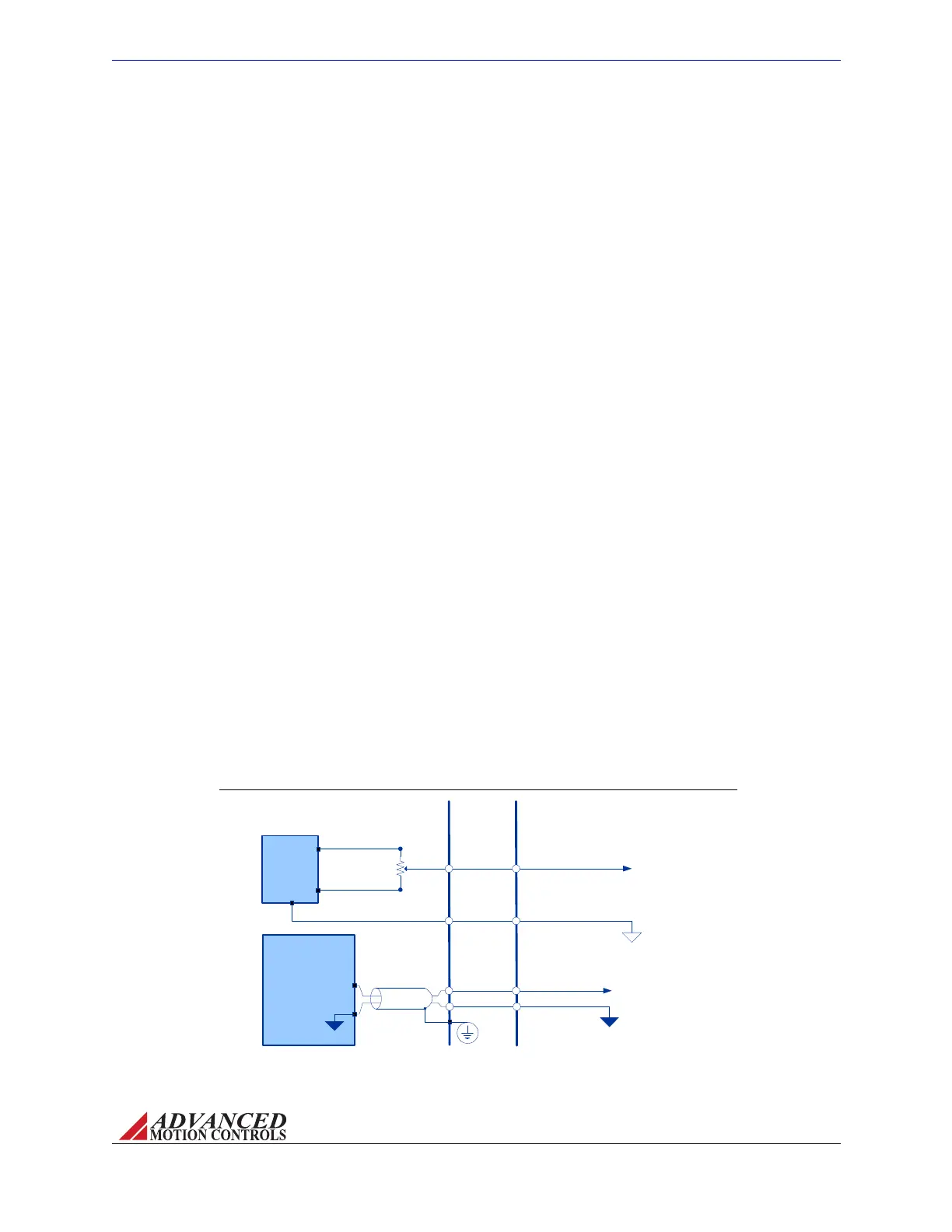
FIGURE 4.1
AZ SERVO
DRIVE
+10V Max
Potentiometer
(~50kO)
-10V Max
+REF IN (P1-1)
+/- VDC
“Test” Power
Supply
+
-
INTERFACE
PCB
Main DC
Power
Supply
POWER GROUND
HIGH VOLTAGE
GND
HIGH
VOLTAGE
GND
SIGNAL GROUND (P1-2)
Reference Input Potentiometer
Input Command Wiring Followtheinstructionsbelowtoproperlywiretheinputcommand
oftheAZdrive,butdonotapplyanypowerorinputsignalyet.
• Fordrivesthatuse+/‐10Vanaloginput,onemethodoftestingthefunctionalityoftheAZ
drivewithinthesystemisbyusinganexternalreferencepotentiometer(approximately50
kΩ)asaninputcommandsignal.ByapplyingapositiveDCvoltage(10Vmax)tooneend
ofthepotentiometer,andanegativeDCvoltage(10Vmax)totheotherendofthe
potentiometer,a+/‐analogsignalcanbesentthroughthepotentiometer’swiperintothe
+REFinputpin,P1‐1,onthemountingcardorPCBinterface(seedrivedatasheetor
“Pinouts”onpage12forpinlabels).Thevoltagesappliedtotheexternalreference
potentiometershouldcomefroma"test"powersupplythatisdiff
erentthanthemainDC
power.Thisseparate+/‐VDC"test"powersupplyshouldbereferencedtotheAZdrive
signalground.
Artisan Technology Group - Quality Instrumentation ... Guaranteed | (888) 88-SOURCE | www.artisantg.com