MNALAZIN-02 24
Integration in the Servo System / Mounting
PCB Mounting Options
AZservodrivescanbedirectlyintegratedontoaPCB,eitherbymountingtheboardonsocket
connectorsorbyactuallysolderingtheAZdrivetotheboard.
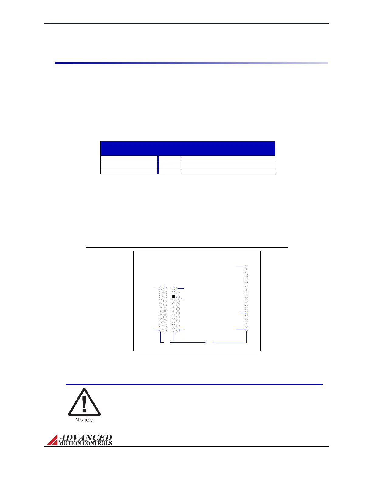
FIGURE 3.4 AZ Drive PCB Footprint
PIN 1b
PIN 1a
PIN 1b
PIN 11b
PIN 11a
P3 - Power
Connector
P2 - Power
Connector
PIN 1a
PIN 11a
PIN 11b
PIN 1
PIN 16
P1 - Signal
Connector
60X 0.025in [0.64mm] SQ Post Thru
[55.88mm]
[10.16mm]
2.20in
0.40in
P2-3a Keyed
Mating Connectors AZdrivesuse0.64mmsquarepostmaleheaders(2.54mmpinspacing)
forsignalandpowerpinsthataredesignedforfastandeasyremovalfromPCB‐mountsocket
connectors,makingthisoptionparticularlyusefulwhenprototyping.Thesocketmating
connectorscompatiblewithAZdrivesareshowninthetablebelow.Fordetailedphysical
dimensions,see“PhysicalDimensions”onpage39.
TABLE 3.2 AZ
Drives Socket Mating Connectors
AZ Socket Mating Connectors
Connector Pins Manufacturer and Part Number
Signal Connector - All AZ Drives 16 Samtec: BCS-116-L-S-PE
Power Connector - AZ6 and AZ12 11 Samtec: BCS-111-L-S-PE
Power Connector - AZ20 22 Samtec: SSM-111-L-DV
AZdrivesaredesignedwithacommonpinlayoutthroughouttheentiredrivefamily,providing
theuserwiththeoptionofdesigningonlyonemountingcardorPCBinterfacethatis
compatiblewitheveryAZdrive.Foranapplicationthatmayhavedifferentversionswith
higherorlowerpowerrequirements,thesamemountingcardorPCBinterfacecanbeusedfor
eachapplicationversionwiththeappropriateAZdrive.ThediagrambelowshowsthePCB
mountingfootprintfortheentireAZfamily.Forspecificdimensions,seeFigureA.3on
page40.
AZ6andAZ12drivemodelsconnecttoP1andthe"A"rowofP2,whileAZ20drivesconnectto
P1andbothrowsofP2.HigherpowerAZmodelsplannedforthefuturewillconnecttoP1,P2,
andP3.
The MC1XAZ01 contains a "keyed" sock
et connector on P2 to coincide
with the "keyed" power header on AZ drives. It is recommended to
include this feature on user designed mounting cards as well in order to
avoid connecting the drive with the wrong orientation.
Artisan Technology Group - Quality Instrumentation ... Guaranteed | (888) 88-SOURCE | www.artisantg.com