Home
Advantech
Motherboard
AIMB-276
Page 62
Advantech AIMB-276 - Page 62
122 pages
Manual
Save Page as PDF
To Next Page
To Next Page
To Previous Page
To Previous Page
Loading...
AIMB-276 Us
er Manual
50
–
Serial Port [ Enabled
]
–
Device Settings: IO=2F8h; IRQ =3
–
Change Setting [ Auto ]
T
o select an optimal setting for serial port 2.
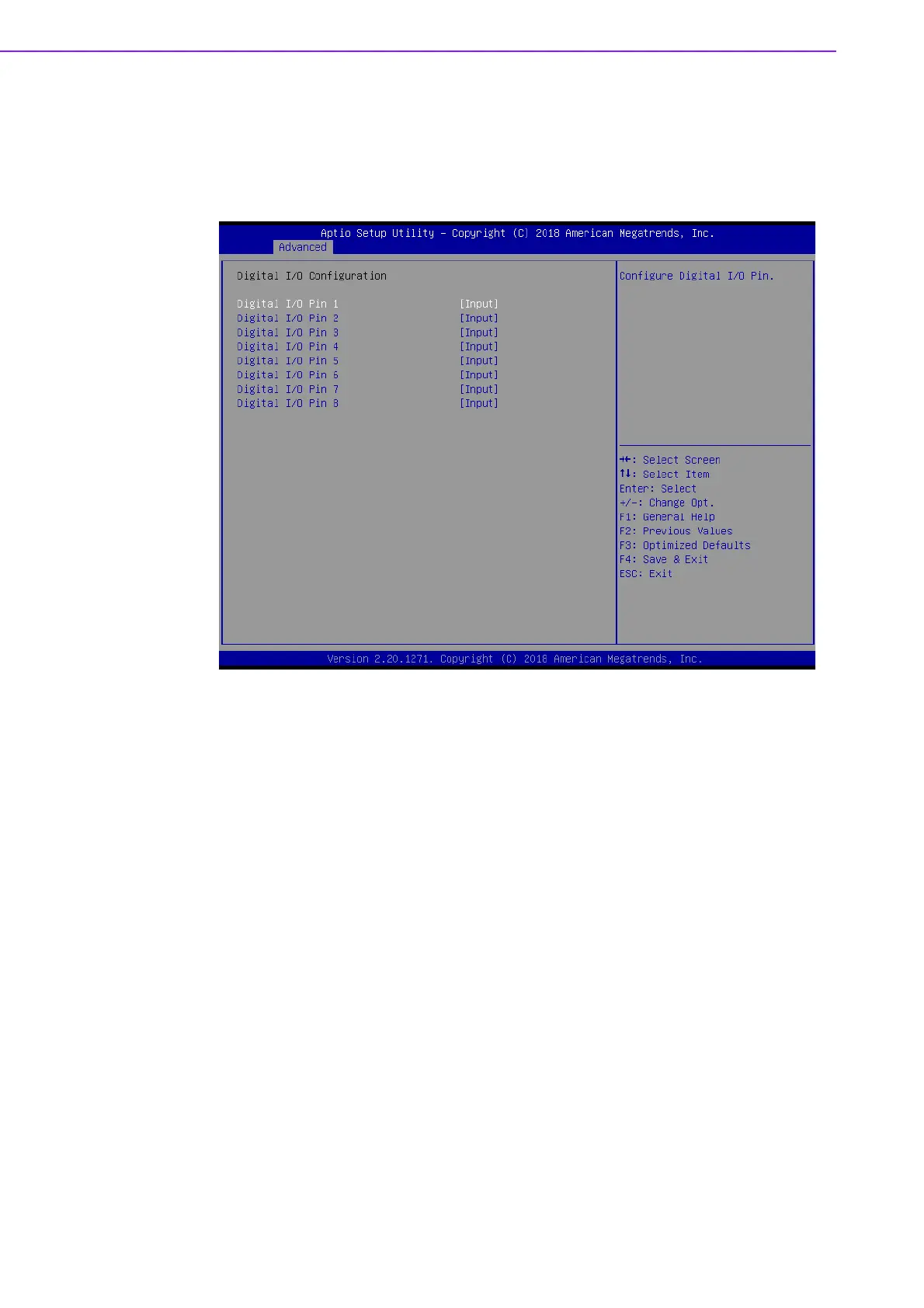
Digit
al I/O Configuration
Digit
al I/O Pin 1 - 8 [ Input ]
61
63
Table of Contents
Main Page
Default Chapter
9
Table of Contents
9
Chapter 1 General Information
13
Introduction
14
Features
14
Specifications
14
System
14
Memory
14
Input/Output
14
Graphics
15
Ethernet LAN
15
Industrial Features
15
Mechanical and Environmental Specifications
15
Jumpers and Connectors
16
Board Layout: Jumper and Connector Locations
21
AIMB-276 Board Diagram
23
Safety Precautions
24
Jumper Settings
24
How to Set Jumpers
24
CMOS Clear (CMOS1)
25
Power Switch/Hdd Led/Smbus/Speaker Pin Header (JFP1)
25
Power LED and Keyboard Lock Pin Header (JFP2)
25
Watchdog Timer Output and OBS Beep (JWDT1+JOBS1)
26
(Jwdt1+Jobs1)
26
ATX/AT Mode Selection (PSON1)
26
LVDS Panel Voltage Selection (JLVDS1)
27
COM2 RI# Pin RI#/5V/12V Select (JSETCOM2_V1)
27
System Memory
27
Memory Installation Procedures
28
Cache Memory
28
Processor Installation
28
Chapter 2 Connecting Peripherals
29
Introduction
30
USB Ports (LAN1_USB12/LAN2_USB34/USB56/USB78/USB910)
30
Displayport1/2 (DP12) / High-Definition Multimedia Interface Connector (HDMI1)
31
Serial Ports (COM1~COM2)
32
CPU Fan Connector (CPU_FAN1)
33
System FAN Connector (SYSFAN1/2)
34
Power Switch/Hdd Led/Smbus/Speaker Pin Header (JFP1) & Power
35
LED and Keyboard Lock Pin Header (JFP2)
35
ATX Soft Power Switch (JFP1/PWR_SW)
35
Reset (JFP1/RESET)
35
Hdd Led (Jfp1/Hddled)
35
External Speaker (JFP1/SPEAKER)
35
DC Input Phoenix Connector (DCIN1)
36
SATA Signal & Power Connector (SATA1~SATA3 / SATA_PWR1~2)
37
HD Analog Audio Interface (AUDIO1, FPAUD1)
38
PCI-E X16 Slot (PCIEX16_1)
39
Low-Voltage Differential Signaling Interface/Embedded Display Port (LVDS_EDP1)
40
LVDS Backlight Inverter Power Connector (INV1)
41
NGFF M.2 B-Key & E-Key Connector (M2B1 & M2E1)
42
Audio Amplifier Output Connector (AMP1), BOM Optional
44
General Purpose I/O Pin Header (GPIO1)
45
SPI BIOS Flash Socket (SPI1)
46
SPI Programming Pin Header (SPI_CN1)
47
Low Pin Count Header (LPC1)
48
Case-Open Detect Connector (JCASE1)
49
CMOS Battery Connector (BAT1)
50
CPU Socket (CPU1)
51
DDR4 SO-DIMM Socket (DIMMA1, DIMMB1)
52
Chapter 3 BIOS Operation
53
Introduction
54
BIOS Setup
54
Main Menu
55
Advanced BIOS Features
55
Chipset Configuration Setting
69
System Agent (SA) Configuration
70
PCH-IO Configuration
74
Security Setting
79
Boot Setting
80
Save & Exit Configuration
81
Chapter 4 Software Introduction & Service
83
Introduction
84
Value-Added Software Services
84
Software API
84
Software Utility
86
Chapter 5 Chipset Software Installation Utility
87
Before You Begin
88
Introduction
88
Windows 10 Driver Setup
89
Chapter 6 VGA Setup
91
Introduction
92
Windows 10
92
Chapter 7 LAN Configuration
93
Introduction
94
Features
94
Installation
94
Windows 10 Driver Setup
95
Appendix A I/O Pin Assignments
97
Direct Current Input Connector (DCIN1)
98
Displayport1/2 (DP12)
98
High-Definition Multimedia Interface Connector (HDMI1)
99
Universal Serial Bus Port 3.1 Gen1 #7/ #8 (USB78)
99
Universal Serial Bus Port 3.1 Gen2 #1/ #2 (USB12)
100
Rj45 #1(Lan1)
100
Universal Serial Bus Port 3.1 Gen2 #3/ #4 (USB34)
101
Rj45 #2(Lan2)
101
Universal Serial Bus Port 3.1 Gen2 #6 (Type-C) (USB6)
101
Universal Serial Bus Port 3.1 Gen2 #5 (USB5)
102
HD Audio Interface (Analog) (AUDIO1)
102
Amplifier Connector (AMP1)
103
Front Panel Audio Header (FPAUD1)
103
CMOS Mode Selection (JCMOS1)
103
PCI Express X16 Slot (PCIEX16_1)
104
CMOS Battery Connector (BAT1)
106
Case Open Connector (JCASEOP_SW1)
106
Case Open Connector (JCASE1)
107
NGFF M.2 B-Key Connector for 2242/3042 Module (M2B1)
107
Universal Serial Bus Port 3.1 Gen1 #9/ #10 Box Header (USB910)
108
COM1 RI# Selection Pin Header (JSETCOM1_V1)
109
Serial ATA Interface Connector #1~#3 (SATA1~SATA3)
109
COM2 Pin Header ( S1.27MM) (COM2)
110
EDP/LVDS Backlight Inverter Power Connector (INV1)
110
COM1 Pin Header ( S1.27MM) (COM1)
111
Low Pin Count Interface Connector (LPC1)
111
Subscriber Identity Module Connector (SIM1)
112
LVDS VESA, JEIDA Format Selection Pin Header (JLVDS_VCON1)
112
Low-Voltage Differential Signaling Interface/Embedded Displayport (LVDS_EDP1)
113
Voltage Selection for JLVDS Connector (JLVDS1)
114
System Fan #1 Connector /System Fan #2 Connector (SYSFAN1/2)
114
Power LED and Keyboard Lock Pin Header (JFP2)
115
Watchdog Timer Output and OBS Beep (JWDT1+JOBS1)
115
CPU FAN Connector (CPUFAN1)
115
8-Bits General Purpose I/O Pin Header( S1.27MM) (GPIO1)
116
PWRBTN#/ RESET#/HDD LED/ Serial Bus from HW Monitor IC/Internal Buzzer / External Speaker Header (JFP1)
116
SPI BIOS Flash Socket (SPI1)
117
Serial ATA Interface Power Connector (SATA_PWR1/2)
117
AT/ATX Mode Selection (PSON1)
118
ATX Supported 3-Pin Header on Board (ATX_5VSB1)
118
NGFF M.2 E-Key Connector for 2230 Module (M2E1 )
119
Related product manuals
Advantech AIMB-275
142 pages
Advantech AIMB-240 Series
99 pages
Advantech AIMB-742
124 pages
Advantech AIMB-780
108 pages
Advantech AIMB-763
66 pages
Advantech AIMB-784
114 pages
Advantech AIMB-785
116 pages
Advantech AIMB-581
112 pages
Advantech AIMB-785G2-00A2
116 pages
Advantech ASMB-585
122 pages
Advantech ASMB-785
128 pages
Advantech ASMB-784
112 pages